1
2
3
4
5
6
7
8
9
10
11
12
13
14
15
16
17
18
19
20
21
22
23
24
25
26
27
28
29
30
31
32
33
34
35
36
37
38
39
40
41
42
43
44
45
46
47
48
49
50
51
52
53
54
55
56
57
58
59
60
61
62
63
64
65
66
67
68
69
70
71
72
73
74
75
76
77
78
79
80
81
82
83
84
85
86
87
88
89
90
91
92
93
94
95
96
97
98
99
100
101
102
103
104
105
106
107
108
109
110
111
112
113
114
115
116
117
118
119
120
121
122
123
124
125
126
127
128
129
130
131
132
133
134
135
136
137
138
139
140
141
142
143
144
145
146
147
148
149
150
151
152
153
154
155
156
157
158
159
160
161
162
163
164
165
166
167
168
169
170
171
172
173
174
175
176
177
178
179
180
181
182
183
184
185
186
187
188
189
190
191
192
193
194
195
196
197
198
199
200
201
202
203
204
205
206
207
208
209
210
211
212
213
214
215
216
217
218
219
220
221
222
223
224
225
226
227
228
229
230
231
232
233
234
235
236
237
238
239
240
241
242
243
244
245
246
247
248
249
250
251
252
253
254
255
256
257
258
259
260
261
262
263
264
265
266
267
268
269
270
271
272
273
274
275
|
---
description: "Custom split ortholinear 83 key mechanical keyboard with rollerball mouse"
created: 2023-10-23
---

[TOC]
## Links
- [git.node5.net - Firmware](https://git.node5.net/firmware/qmk/tree/keyboards/handwired/node5_1)
### Videos
- [youtube.com - Good how to video](https://www.youtube.com/watch?v=iv__343ZwE0)
- [youtube.com - Zack Freedman (Voidstar Lab) How to Build MECHANICAL KEYBOARDS](https://www.youtube.com/watch?v=yYcNi9hKxDk)
### Parts
- [shop.pimoroni.com - Trackball Breakout by Pimoroni](https://shop.pimoroni.com/products/trackball-breakout)
- [aliexpress.com - 1N4148 diodes](https://www.aliexpress.com/item/1005005435418695.html)
### Others cool builds
- [keebfolio.netlify.app - Index of handwired keyboards](https://keebfolio.netlify.app/en/staggered/)
- [lukemillermakes.com - A 3D printed gaming keyboard](https://www.lukemillermakes.com/2018/12/a-3d-printed-gaming-keyboard-part-1/)
- [github.com - Hand wired 54key full split mechanical keyboard](https://github.com/alonswartz/blackhawk)
### Tools
- [form--keebfolio.netlify.app - Collection of great tools](https://form--keebfolio.netlify.app/tools/)
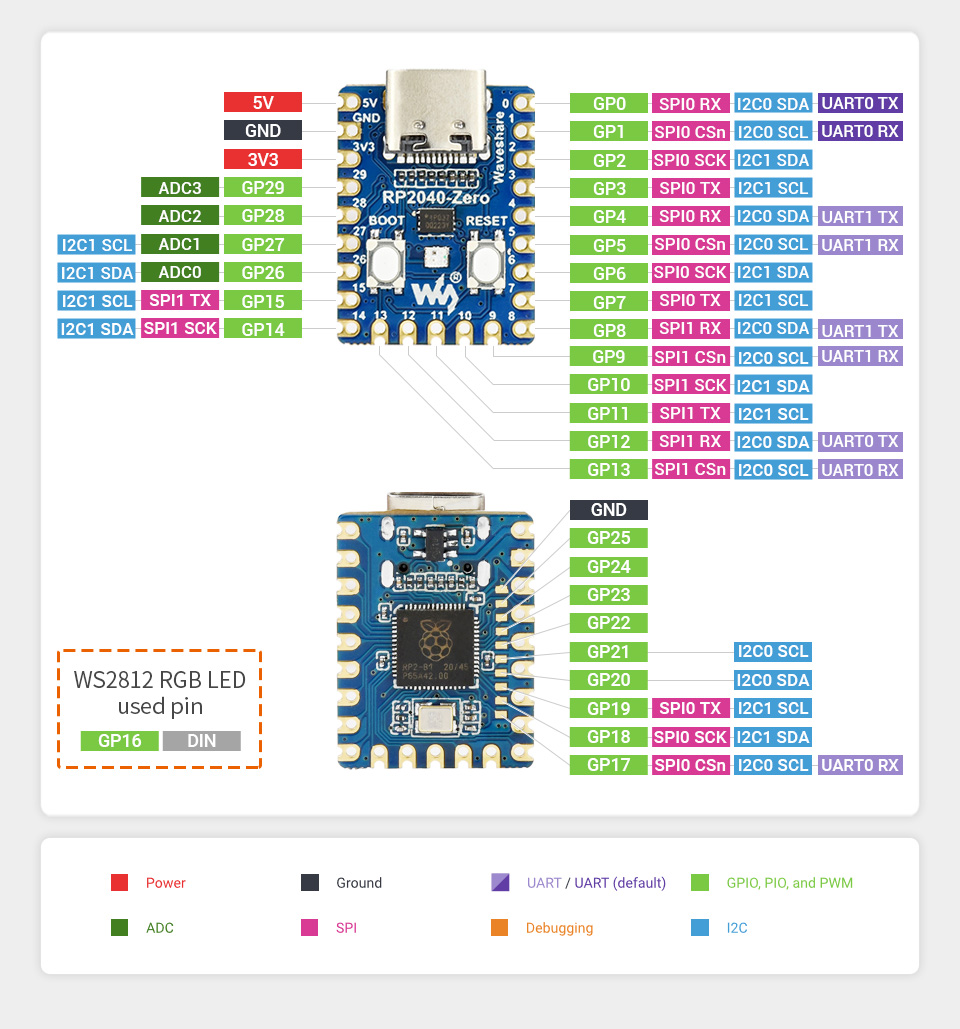
- [waveshare.com - RP2040-Zero pinout](https://www.waveshare.com/img/devkit/RP2040-Zero/RP2040-Zero-details-7.jpg)
- [keyboard-layout-editor.com - My layout](http://www.keyboard-layout-editor.com/##@_backcolor=%23000000%3B&@_c=%230096a7&t=%23ffffff%0A%0A%0A%23ff8616%3B&=Esc%0A%0A%0AFnLock&_c=%236d6d6d%3B&=F1%0A%0A%0A%3Ci%20class%2F='fa%20fa-volume-off'%3E%3C%2F%2Fi%3E&=F2%0A%0A%0A%3Ci%20class%2F='fa%20fa-volume-down'%3E%3C%2F%2Fi%3E&=F3%0A%0A%0A%3Ci%20class%2F='fa%20fa-volume-up'%3E%3C%2F%2Fi%3E&=F4%0A%0A%0A%3Ci%20class%2F='fa%20fa-microphone-slash'%3E%3C%2F%2Fi%3E&=F5%0A%0A%0A%3Ci%20class%2F='fa%20fa-sun-o'%3E%3C%2F%2Fi%3E-&_x:3%3B&=F6%0A%0A%0A%3Ci%20class%2F='fa%20fa-sun-o'%3E%3C%2F%2Fi%3E+&=F7%0A%0A%0A%3Ci%20class%2F='fa%20fa-caret-left'%3E%3C%2F%2Fi%3E%3Ci%20class%2F='fa%20fa-caret-left'%3E%3C%2F%2Fi%3E&=F8%0A%0A%0A%3Ci%20class%2F='fa%20fa-play'%3E%3C%2F%2Fi%3E%3Ci%20class%2F='fa%20fa-pause'%3E%3C%2F%2Fi%3E&=F9%0A%0A%0A%3Ci%20class%2F='fa%20fa-caret-right'%3E%3C%2F%2Fi%3E%3Ci%20class%2F='fa%20fa-caret-right'%3E%3C%2F%2Fi%3E&_t=%23ffffff%3B&=F10&=F11&=F12&=Delete%3B&@_c=%23262626%3B&=%60%0A~&=1%0A!&=2%0A%2F@&=3%0A%23&=4%0A$&=5%0A%25&_x:3%3B&=6%0A%5E&_t=%23ffffff%0A%0A%0A%23ff8616%3B&=7%0A%2F&%0A%0A7&=8%0A*%0A%0A8&=9%0A%28%0A%0A9&=0%0A%29%0A%0A+&_t=%23ffffff%3B&=-%0A%2F_&=%2F=%0A+&_c=%236d6d6d%3B&=BckSp%3B&@=Tab&_c=%23262626%3B&=Q&=W&=E&=R&=T&_x:3%3B&=Y&_t=%23ffffff%0A%0A%0A%23ff8616%3B&=U%0A%0A%0A4&=I%0A%0A%0A5&=O%0A%0A%0A6&=P%0A%0A%0A%C3%97&_t=%23ffffff%3B&=%7B%0A%5B&=%7D%0A%5D&=%7C%0A%5C%3B&@_c=%236d6d6d&t=%23ffffff%0A%0A%0A%23ff8616%3B&=Comp%0A%0A%0ACapsL&_c=%23262626&t=%23ffffff%3B&=A&=S&=D&_n:true%3B&=F&=G&_x:3%3B&=H&_t=%23ffffff%0A%0A%0A%23ff8616&n:true%3B&=J%0A%0A%0A1&=K%0A%0A%0A2&=L%0A%0A%0A3&=%2F:%0A%2F%3B%0A%0A-&_t=%23ffffff%3B&=%22%0A'&_c=%230096a7&w:2%3B&=Enter%3B&@_c=%236d6d6d%3B&=Shift&_c=%23262626%3B&=Z&=X&=C&=V&=B&_x:3%3B&=N&_t=%23ffffff%0A%0A%0A%23ff8616%3B&=M%0A%0A%0A0&=%3C%0A,%0A%0A,&=%3E%0A.%0A%0A.&=%3F%0A%2F%2F%0A%0A%2F%2F&_c=%236d6d6d&t=%23ffffff%3B&=PgUp&_c=%23c1c1c1&t=%23000000%3B&=%E2%86%91&_c=%236d6d6d&t=%23ffffff%3B&=PgDn%3B&@=Ctrl&=Super&=Alt&_t=%23ff8616%3B&=Fn&_c=%23262626&t=%23ffffff&a:7&w:2%3B&=&_x:2&c=%23c1c1c1&t=%23000000&a:4%3B&=mous1&=mous2&=mous3&_c=%236d6d6d&t=%23ffffff%0A%0A%0A%23ff8616%3B&=Menu%0A%0A%0AInsert&=Home%0A%0A%0APrtSc&_t=%23ffffff%3B&=End&_c=%23c1c1c1&t=%23000000%3B&=%E2%86%90&_n:true%3B&=%E2%86%93&=%E2%86%92)
### Guides
- [crackedthecode.co - Someone elses cool blog on how to wire a keyboard matrix](https://www.crackedthecode.co/a-complete-guide-to-building-a-hand-wired-keyboard/)
---
# Design / concept validation phase
The idea some time ago when i was playing around with ideas for my cyber deck,
to design a keyboard.
I ended up splitting the keyboard idea out and focusing on that.
I played around with the layout for some time using
[keyboard-layout-editor.com](http://keyboard-layout-editor.com/)
Finally landing on a layout i liked, with some concepts i wanted to try out.

## Verifying design concepts
If there's any unknowns in your project, you should try them out early in the
process, this can save you a lot of time and hazzle.
### Generation + tollerance fit check


### Connecting the 2 sides
There's multiple ways of connecting the 2 sides of the keyboard namely:
I²C (4 wire, typically a 3.5mm audio cable) via seperate micro controller or
I/O expander or have a cable with many conductors.
Contrary to [this video](https://www.youtube.com/watch?v=Fg0V5M0llaE&t=342s) by
[Zack Freedman (Voidstar Lab)](https://www.youtube.com/@ZackFreedman)
i like rainbow cables.

Didn't want to wait for a shipment from China, so i made a connector for my
rainbow cable, the case design, didn't quite fit the
connector, i fixed it in post.
### Switch plate
The switch plate was generated using
[kbplate.ai03.com](https://kbplate.ai03.com/)
### Left side initial
Designed and printed the left side of the keyboard.

This is the point where i should have chosen to throw out the first prototype,
since the connector didn't fit. And it was going to be nightmare to have wires
between the two halves. This will come back to haunt me later.
### Keycaps
Found [this](https://www.thingiverse.com/thing:2879386) design i liked,
but i encoundered a problem with it, it snagged when pressing down. So i
[modified the design in FreeCAD as an STL](https://www.youtube.com/watch?v=HbtKFmz5p00)
, as importing it as openSCAD and then modifying gave me issues.
It now has a slope along the long side of the key switch rectangle.


The 2 unit wide keys can be made in
[PrusaSlicer](https://www.prusa3d.com/page/prusaslicer_424/) by cutting it into
parts and scaling only the desired part in the desired dimension.
The homing indicator, can also simply be made in PrusaSlicer.
When printing, place the keycaps sideways on the build plate, as to use the
dimension with the best resulution in FDM printing (Set layer height to the
smallest possible). And make sure the top parts of the keycaps are facing away
from each other, if printing multiple, to avoid stringing, bumps and other
artifacts.
The keycaps still require quite a lot of cleanup, as there's some drop in the
stem connector, and some cutting and filing is needed on the side of the stem
where the support was.
### Wiring

This overview was made with [VIA](https://www.caniusevia.com/)
The column wires can be managed by routing them under the diodes from the rows.

I'd recomend staring with wiring a 3x3 matrix and connecting that on a
breadboard to your microcontroller, and try
[building the firmware](#firmware-build). To verify the method and avoiding
possibly having to resolder big parts.
---
# Build phase
There are now no known unknowns in the project, now comes the grind.
### Left side done


Since i decided to use the first prototype, i had to retrofit the connector
outside the housing, meaning i had to design a new piece that a connector i
found, could be press fit into.
### Left side done right side WIP

## Right side


When soldering the connector, i soldered wires to the connector first, then i
glued in indo place, so the wires could be routed and cut to distance.
All 20 trough-hole GPIO pins on the micro controller chip breakout are needed
for the 6 rows and 14 columns, but 2 GPIO are needed for I²C for the trackball.
So i needed to access the SMD pads on the back of the RP2040, which was some
small soldering, i used a flat cable to achive this.
Another problem is that the prototyping PCB the microcontroller is mounted into
isn't used for wire management, but meerly to attatch it with screwable mounting
holes to the case. This means i have to have lot's of small wires in a tight
space this is where [Magnet wire](https://en.wikipedia.org/wiki/Magnet_wire)
comes into play.
## Firmware build
[Setting Up Your QMK Environment](https://docs.qmk.fm/#/newbs)
When creating a handwired keyboard, the convention is to place it
in `handwired/name`
You might have to flip `diode_direction` in `info.json` if no keys work.
The options are `ROW2COL` and `COL2ROW`
### Customizing firmware
It's possible to [Customize Your Keyboard’s Behavior](https://docs.qmk.fm/#/custom_quantum_functions)
by writing a bit of C code.
I've coded the following:
- Change pointing device CPI. by clicking it
- Indicate pointing device mode with its RGB LED
- Normal
- Precise
- Scroll
- Volume
- Switch layout (Colemak, qwerty)
- Turn LEDs off when suspending / shutting down computer
- Middle mouse button only send button press on button up, if the user didn't scroll
The way i figured out how to do something specific,
was a combination of reading the documentation, and greping through how other
keyboards in the `keyboards` directory does things.
TODO Host, post and add link to GIT repo
## Next challenge learning colemak
It's a steep learning curve, but the finger movement, or lack there of for
typing English seems more sound. Set aside a weekend for learning where the
keys are, and be prepared to be frustrated at typing at 5 wpm, and slowly
working up from there.
It's a bit unfortunate that I'm changing multiple variables at the same time,
Namely learning touch typing, at the same time as i switch to colemak
and an ortholinear layout. Therefore i will not know which impact each has on
percieved finger health and typing speed.
Also small rant about the legacy typewriter layout that sadly is the norm now
adays. How are you supposed to twist and contort your middle finger to reach
from D on the home row to C below when your hands are so close together that
they aren't straight. It feels more natural for my pointing finger to reach the
C button, because it aligns with the direction my hands are pointing.
## Retrospective / Ideas for a version 2
### Work methodologies
Before starting a handwired keyboard project know that:
- It's very labor intensive
- Hand wiring will take a long time especially if you make a split keeb, and choose to not use I²C between the halves.
- When prototyping something it's an itterative process,
which 3D printing plays very well into, as you can rapidly prototype, test ideas, and modify your design.
### Scrolling / volume rollers
Scrolling and adjusting volume with the trackball works great.
It would be awesome to explore this concept more,
by having a dedicated rotary encoder for it, perhaps two,
for quick onehanded volume adjustment, without holding the modifier (FN),
which is on the other side of the keyboard.
### Device specific LED indicators
The LED in the pimoroni trackball works great to indicate which mode it's in.
So having dedicated LEDs for each device,
to indicate which mode it's in is a great to have.
### LED indicators
They work great as a layer indicator.
Another idea is to add a photo resistor to dimm them in low ambient.
### Pimoroni trackball
It's a really nifty little device, glad i tried it out,
but it's not precise enough for my taste.
It might be the QMK implementation (which already existed, which is nice),
It might be a hardware thing. Not sure, haven't read raw device output,
i assume default QMK settings are sane.
But next time around i want to try a different pointing device,
perhaps a ThinkPad trackpoint.
### Connector / cable / wiring management
It worked fine for the time, since i had plenty of time to work on it now,
and didn't have to wait for components.
The process of hand wiring is labor intensive and tedious work.
Managing the wiring in a PCB and using chips in each half,
with standard cables would be preferable.
Then it's also possible to use longer cables to position the keyboard on either
side of a laptop, when using it on the go.
Taking up less space in one dimmension, but more in another,
by not having to move the laptop as far back, giving you flexibility.
### Touch typing colorway
The keycaps can be colored to indicate which finger should be used.
This could also be done in software, if one chooses to add per key LEDs.
### Standoffs on switch plate
Designing the standoffs into the switch plate might be desirable, since it
can make the cable wiring a bit easier,
### Macro recording indicator
QMK Has the ability to record
[Dynamic macros](https://docs.qmk.fm/#/feature_dynamic_macros)
It would be cool to indicate the recording of such, by blinking the main
indicator LED red, this requires the ability to get
[milis()](https://www.arduino.cc/reference/en/language/functions/time/millis/)
or similar.
### Sub par typing experience, due to keycap profile and switch type
I'm not satisfied with the typing experience, the keycaps leave very little space between the keys, which amounts to not
easily being able to easily find the center of the key quickly, and with little cognitive overhead.
Thus resulting in miss clicks, this matched with the assortment of bad key switches leads a subpar and frustrating
typing experience. This is fine tho, because the first iteration serves as the biggest learning test bed, to see what
works. I'd argue for intentionally making a prototype without all the nice finishing work,
and using it for a while, to see which concepts work
|
