
diff options
| author | user <user@node5.net> | 2024-03-11 11:31:58 +0100 |
|---|---|---|
| committer | user <user@node5.net> | 2024-03-11 11:31:58 +0100 |
| commit | 1ede08d1790d1046c06343f273711fe68ab62f83 (patch) | |
| tree | 5270392ffa4cbed5598f5aeca1b6f86171db8626 | |
initial commit with 18 articles


139 files changed, 1150 insertions, 0 deletions
diff --git a/3D printing copenhagen/DHM_correction.jpg b/3D printing copenhagen/DHM_correction.jpg Binary files differnew file mode 100644 index 0000000..99ae29e --- /dev/null +++ b/3D printing copenhagen/DHM_correction.jpg diff --git a/3D printing copenhagen/Thumbnail.jpg b/3D printing copenhagen/Thumbnail.jpg Binary files differnew file mode 100644 index 0000000..f4020c1 --- /dev/null +++ b/3D printing copenhagen/Thumbnail.jpg diff --git a/3D printing copenhagen/big_scale.jpg b/3D printing copenhagen/big_scale.jpg Binary files differnew file mode 100644 index 0000000..67e2dc3 --- /dev/null +++ b/3D printing copenhagen/big_scale.jpg diff --git a/3D printing copenhagen/index.md b/3D printing copenhagen/index.md new file mode 100644 index 0000000..05ac8f4 --- /dev/null +++ b/3D printing copenhagen/index.md @@ -0,0 +1,44 @@ +--- +description: "Height data converted and 3D printed as wall art" +created: 2022-12-21 +--- + + + +- Data: [Danmarks Højdemodel - Overflade](https://dataforsyningen.dk/data/928) (GEOTIFF) +- Processing software: [QGIS Desktop](https://www.qgis.org) +- Plugins: [DEMto3D](https://demto3d.com), [Layer Group and Sort](https://plugins.qgis.org/plugins/Group_and_Sort_Layers) + + + +Digital Height Model loaded in QGIS + + + + +Sliced in: [PrusaSlicer](https://www.prusa3d.com/prusaslicer/) + + + + +Scale: 1:7500 10x10 cm 750x750 m + + + + +Testing seams + + + + +Testing scale + + + + + +Indeholder data fra Styrelsen for Dataforsyning og Infrastruktur, +[Dataforsyningen data license and usage rights](https://dataforsyningen.dk/asset/PDF/rettigheder_vilkaar/Vilk%C3%A5r%20for%20brug%20af%20frie%20geografiske%20data.pdf), +Danmarks Højdemodel, +July 2023 + diff --git a/3D printing copenhagen/kastellet_DHM.jpg b/3D printing copenhagen/kastellet_DHM.jpg Binary files differnew file mode 100644 index 0000000..027472e --- /dev/null +++ b/3D printing copenhagen/kastellet_DHM.jpg diff --git a/3D printing copenhagen/kastellet_printed.jpg b/3D printing copenhagen/kastellet_printed.jpg Binary files differnew file mode 100644 index 0000000..f3b5b02 --- /dev/null +++ b/3D printing copenhagen/kastellet_printed.jpg diff --git a/3D printing copenhagen/kastellet_sliced.jpg b/3D printing copenhagen/kastellet_sliced.jpg Binary files differnew file mode 100644 index 0000000..a96b3d8 --- /dev/null +++ b/3D printing copenhagen/kastellet_sliced.jpg diff --git a/3D printing copenhagen/main.jpg b/3D printing copenhagen/main.jpg Binary files differnew file mode 100644 index 0000000..099a785 --- /dev/null +++ b/3D printing copenhagen/main.jpg diff --git a/3D printing copenhagen/politi_gården.jpg b/3D printing copenhagen/politi_gården.jpg Binary files differnew file mode 100644 index 0000000..6b3114b --- /dev/null +++ b/3D printing copenhagen/politi_gården.jpg diff --git a/3D printing copenhagen/test_seam.jpg b/3D printing copenhagen/test_seam.jpg Binary files differnew file mode 100644 index 0000000..f0d0e0e --- /dev/null +++ b/3D printing copenhagen/test_seam.jpg diff --git a/Arts and crafts/Embroidery/Alderaan.jpg b/Arts and crafts/Embroidery/Alderaan.jpg Binary files differnew file mode 100644 index 0000000..7d3efef --- /dev/null +++ b/Arts and crafts/Embroidery/Alderaan.jpg diff --git a/Arts and crafts/Embroidery/Copenhagen local trains.jpg b/Arts and crafts/Embroidery/Copenhagen local trains.jpg Binary files differnew file mode 100644 index 0000000..aa9c6c6 --- /dev/null +++ b/Arts and crafts/Embroidery/Copenhagen local trains.jpg diff --git a/Arts and crafts/Embroidery/Death star Alderaan.jpg b/Arts and crafts/Embroidery/Death star Alderaan.jpg Binary files differnew file mode 100644 index 0000000..873aaf1 --- /dev/null +++ b/Arts and crafts/Embroidery/Death star Alderaan.jpg diff --git a/Arts and crafts/Embroidery/Death star sketch.jpg b/Arts and crafts/Embroidery/Death star sketch.jpg Binary files differnew file mode 100644 index 0000000..9183ff5 --- /dev/null +++ b/Arts and crafts/Embroidery/Death star sketch.jpg diff --git a/Arts and crafts/Embroidery/Skeleton bongo cat BMTH.jpg b/Arts and crafts/Embroidery/Skeleton bongo cat BMTH.jpg Binary files differnew file mode 100644 index 0000000..0dab59d --- /dev/null +++ b/Arts and crafts/Embroidery/Skeleton bongo cat BMTH.jpg diff --git a/Arts and crafts/Embroidery/index.md b/Arts and crafts/Embroidery/index.md new file mode 100644 index 0000000..299623c --- /dev/null +++ b/Arts and crafts/Embroidery/index.md @@ -0,0 +1,15 @@ +--- +description: Embroidery +created: 2024-02-01 +--- + + + + + + + + + +I used what i had on hand to sketch namely potato starch flour in water with a brush, this worked surprisingly ok in a +pinch. diff --git a/Blog meta.md b/Blog meta.md new file mode 100644 index 0000000..87410ba --- /dev/null +++ b/Blog meta.md @@ -0,0 +1,18 @@ +--- +description: Information about this blog itself +created: 2023-12-21 +--- + +This blog is a statically generated site derived from markdown files using a +[self made blog generator](https://git.node5.net/blog-generator/about), it used to be generated with jekyll + +This blog has gone through design revisions, try visiting [/old](https://blog.node5.net/old) to see the old design. + +The blog is designed so there's minimal distractions, your attention span only has to follow one line down the page. + +The web is generally pretty annoying to use nowadays, since most pages are mini applications that you download, their +performance is sluggish and generally just employ "features" that get in the way of obtaining the desired information, +requiring cognitive overhead. + +I've made this blog to document my projects, aiding my own information retention, future reference for myself, +and showing off to others diff --git a/Casio watch NFC rainbow film mod/Casio rainbowfilm nfc mod.jpg b/Casio watch NFC rainbow film mod/Casio rainbowfilm nfc mod.jpg Binary files differnew file mode 100644 index 0000000..31cf7f8 --- /dev/null +++ b/Casio watch NFC rainbow film mod/Casio rainbowfilm nfc mod.jpg diff --git a/Casio watch NFC rainbow film mod/Inside.jpg b/Casio watch NFC rainbow film mod/Inside.jpg Binary files differnew file mode 100644 index 0000000..5871647 --- /dev/null +++ b/Casio watch NFC rainbow film mod/Inside.jpg diff --git a/Casio watch NFC rainbow film mod/Thumbnail.jpg b/Casio watch NFC rainbow film mod/Thumbnail.jpg Binary files differnew file mode 100644 index 0000000..5def80b --- /dev/null +++ b/Casio watch NFC rainbow film mod/Thumbnail.jpg diff --git a/Casio watch NFC rainbow film mod/W59 modded front.png b/Casio watch NFC rainbow film mod/W59 modded front.png Binary files differnew file mode 100644 index 0000000..6672e22 --- /dev/null +++ b/Casio watch NFC rainbow film mod/W59 modded front.png diff --git a/Casio watch NFC rainbow film mod/index.md b/Casio watch NFC rainbow film mod/index.md new file mode 100644 index 0000000..9af17a8 --- /dev/null +++ b/Casio watch NFC rainbow film mod/index.md @@ -0,0 +1,27 @@ +--- +description: Modded casio wrist watch with NFC and colorful watch face +created: 2023-12-18 +--- + + + +I modded a Casio W59 with Dichroic film rainbow film and a 2x1 cm NFC sticker, and some crunched up aluminum foil + +Parts: + +- Dichroic film + - [aliexpress.com - Holographic Clear Window Film](https://www.aliexpress.com/item/1005005620190266.html) + - [velken.shop - Rainbow color effect film, cold, transparent](https://www.velken.shop/p/rainbow-color-effect-film-cold-transparent/) +- [aliexpress.com - NFC Chip Ntag 213 Sticker 13.56MHz RFID Size 2*1cm](https://www.aliexpress.com/item/1005006220591444.html) +- [aliexpress.com - Adhesive polarizer](https://www.aliexpress.com/item/1005004269567641.html) note, it's important to get the sticky kind + +NFC sticker tutorial video tutorial: + +[youtube.com - CASIO F-91 NFC MOD - DIY F91W NFC Tag Implant ( Easy Modification )](https://www.youtube.com/watch?v=aGn2_zP8GI8) + +Inverted display video: + +[youtube.com - More Casio Watch Mods (Inverted and Translucent LCD) ](https://www.youtube.com/watch?v=EsO-i5nS1z0) + + +
\ No newline at end of file diff --git a/Cheat sheets/Commands.md b/Cheat sheets/Commands.md new file mode 100644 index 0000000..818710f --- /dev/null +++ b/Cheat sheets/Commands.md @@ -0,0 +1,19 @@ +--- +description: Handy commands i use on my Linux distro machines +created: 2024-01-01 +--- + + +## Convert markdown to HTML +e.g. to preview a markdown file +Reqires [python-markdown](https://python-markdown.github.io/install/) + +```bash +python3 -m markdown README.md > /tmp/README.html +``` + +To load extensions like code blocks: +```bash +python3 -m markdown -x fenced_code -x codehilite -x tables README.md > /tmp/README.html +``` + diff --git a/Cheat sheets/Git.md b/Cheat sheets/Git.md new file mode 100644 index 0000000..5297eda --- /dev/null +++ b/Cheat sheets/Git.md @@ -0,0 +1,12 @@ +--- +created: 2024-01-01 +description: Handy git commands +--- + +### See changes since last commit +```bash +git diff HEAD~0 +``` + +### Commit parts of a file +[filip-prochazka.com - Git: commit only parts of a file](https://filip-prochazka.com/blog/git-commit-only-parts-of-a-file) diff --git a/Custom keyboard V2/2 column modules.jpg b/Custom keyboard V2/2 column modules.jpg Binary files differnew file mode 100644 index 0000000..b3f15ce --- /dev/null +++ b/Custom keyboard V2/2 column modules.jpg diff --git a/Custom keyboard V2/3D printed "PCB" feasability test.jpg b/Custom keyboard V2/3D printed "PCB" feasability test.jpg Binary files differnew file mode 100755 index 0000000..152ec27 --- /dev/null +++ b/Custom keyboard V2/3D printed "PCB" feasability test.jpg diff --git a/Custom keyboard V2/3D printed keycaps with legends.jpg b/Custom keyboard V2/3D printed keycaps with legends.jpg Binary files differnew file mode 100755 index 0000000..435c311 --- /dev/null +++ b/Custom keyboard V2/3D printed keycaps with legends.jpg diff --git a/Custom keyboard V2/3D printed trace groves.jpg b/Custom keyboard V2/3D printed trace groves.jpg Binary files differnew file mode 100755 index 0000000..d1b4bc3 --- /dev/null +++ b/Custom keyboard V2/3D printed trace groves.jpg diff --git a/Custom keyboard V2/3d printing keycaps sideways.jpg b/Custom keyboard V2/3d printing keycaps sideways.jpg Binary files differnew file mode 100644 index 0000000..c34ff2d --- /dev/null +++ b/Custom keyboard V2/3d printing keycaps sideways.jpg diff --git a/Custom keyboard V2/Circuit board painted.jpg b/Custom keyboard V2/Circuit board painted.jpg Binary files differnew file mode 100644 index 0000000..025899f --- /dev/null +++ b/Custom keyboard V2/Circuit board painted.jpg diff --git a/Custom keyboard V2/Circuit initial test.jpg b/Custom keyboard V2/Circuit initial test.jpg Binary files differnew file mode 100644 index 0000000..f4c09b9 --- /dev/null +++ b/Custom keyboard V2/Circuit initial test.jpg diff --git a/Custom keyboard V2/Column module nail indent.jpg b/Custom keyboard V2/Column module nail indent.jpg Binary files differnew file mode 100644 index 0000000..3448d55 --- /dev/null +++ b/Custom keyboard V2/Column module nail indent.jpg diff --git a/Custom keyboard V2/Column module slider foot.jpg b/Custom keyboard V2/Column module slider foot.jpg Binary files differnew file mode 100644 index 0000000..aff2dda --- /dev/null +++ b/Custom keyboard V2/Column module slider foot.jpg diff --git a/Custom keyboard V2/Coulumns modules for left side WIP.jpg b/Custom keyboard V2/Coulumns modules for left side WIP.jpg Binary files differnew file mode 100644 index 0000000..3c9e9af --- /dev/null +++ b/Custom keyboard V2/Coulumns modules for left side WIP.jpg diff --git a/Custom keyboard V2/End stop back.jpg b/Custom keyboard V2/End stop back.jpg Binary files differnew file mode 100644 index 0000000..0f7af7c --- /dev/null +++ b/Custom keyboard V2/End stop back.jpg diff --git a/Custom keyboard V2/Key switch height compared to v1.jpg b/Custom keyboard V2/Key switch height compared to v1.jpg Binary files differnew file mode 100755 index 0000000..13655cb --- /dev/null +++ b/Custom keyboard V2/Key switch height compared to v1.jpg diff --git a/Custom keyboard V2/Keyboard layout.jpg b/Custom keyboard V2/Keyboard layout.jpg Binary files differnew file mode 100644 index 0000000..7e3da3b --- /dev/null +++ b/Custom keyboard V2/Keyboard layout.jpg diff --git a/Custom keyboard V2/Keycaps itterations.jpg b/Custom keyboard V2/Keycaps itterations.jpg Binary files differnew file mode 100644 index 0000000..c70ce4f --- /dev/null +++ b/Custom keyboard V2/Keycaps itterations.jpg diff --git a/Custom keyboard V2/Left side modules in base bottom.jpg b/Custom keyboard V2/Left side modules in base bottom.jpg Binary files differnew file mode 100644 index 0000000..19ff270 --- /dev/null +++ b/Custom keyboard V2/Left side modules in base bottom.jpg diff --git a/Custom keyboard V2/Left side modules in base top.jpg b/Custom keyboard V2/Left side modules in base top.jpg Binary files differnew file mode 100644 index 0000000..d4ba3aa --- /dev/null +++ b/Custom keyboard V2/Left side modules in base top.jpg diff --git a/Custom keyboard V2/Left side wiring diagram.jpg b/Custom keyboard V2/Left side wiring diagram.jpg Binary files differnew file mode 100644 index 0000000..6f34056 --- /dev/null +++ b/Custom keyboard V2/Left side wiring diagram.jpg diff --git a/Custom keyboard V2/Left side wiring diagram.xcf b/Custom keyboard V2/Left side wiring diagram.xcf Binary files differnew file mode 100644 index 0000000..2b792c9 --- /dev/null +++ b/Custom keyboard V2/Left side wiring diagram.xcf diff --git a/Custom keyboard V2/Left side working prototype.jpg b/Custom keyboard V2/Left side working prototype.jpg Binary files differnew file mode 100644 index 0000000..ef4780a --- /dev/null +++ b/Custom keyboard V2/Left side working prototype.jpg diff --git a/Custom keyboard V2/Module wired bottom.jpg b/Custom keyboard V2/Module wired bottom.jpg Binary files differnew file mode 100644 index 0000000..1b31c01 --- /dev/null +++ b/Custom keyboard V2/Module wired bottom.jpg diff --git a/Custom keyboard V2/Module wired top.jpg b/Custom keyboard V2/Module wired top.jpg Binary files differnew file mode 100644 index 0000000..15a1ba0 --- /dev/null +++ b/Custom keyboard V2/Module wired top.jpg diff --git a/Custom keyboard V2/Notes column module idea generation.jpg b/Custom keyboard V2/Notes column module idea generation.jpg Binary files differnew file mode 100755 index 0000000..57aa3e2 --- /dev/null +++ b/Custom keyboard V2/Notes column module idea generation.jpg diff --git a/Custom keyboard V2/Notes idea.jpg b/Custom keyboard V2/Notes idea.jpg Binary files differnew file mode 100755 index 0000000..1290cf1 --- /dev/null +++ b/Custom keyboard V2/Notes idea.jpg diff --git a/Custom keyboard V2/Prototype pile.jpg b/Custom keyboard V2/Prototype pile.jpg Binary files differnew file mode 100644 index 0000000..1c6a165 --- /dev/null +++ b/Custom keyboard V2/Prototype pile.jpg diff --git a/Custom keyboard V2/Screws side view.jpg b/Custom keyboard V2/Screws side view.jpg Binary files differnew file mode 100644 index 0000000..beb1ed9 --- /dev/null +++ b/Custom keyboard V2/Screws side view.jpg diff --git a/Custom keyboard V2/Screws.jpg b/Custom keyboard V2/Screws.jpg Binary files differnew file mode 100644 index 0000000..7e135d8 --- /dev/null +++ b/Custom keyboard V2/Screws.jpg diff --git a/Custom keyboard V2/Slide test 1 slicer 2 lines.png b/Custom keyboard V2/Slide test 1 slicer 2 lines.png Binary files differnew file mode 100755 index 0000000..b414f62 --- /dev/null +++ b/Custom keyboard V2/Slide test 1 slicer 2 lines.png diff --git a/Custom keyboard V2/Slide test 1.png b/Custom keyboard V2/Slide test 1.png Binary files differnew file mode 100755 index 0000000..e5cb59c --- /dev/null +++ b/Custom keyboard V2/Slide test 1.png diff --git a/Custom keyboard V2/Switch holder itterations.jpg b/Custom keyboard V2/Switch holder itterations.jpg Binary files differnew file mode 100755 index 0000000..2541201 --- /dev/null +++ b/Custom keyboard V2/Switch holder itterations.jpg diff --git a/Custom keyboard V2/Switches.jpg b/Custom keyboard V2/Switches.jpg Binary files differnew file mode 100755 index 0000000..de68d1d --- /dev/null +++ b/Custom keyboard V2/Switches.jpg diff --git a/Custom keyboard V2/Thumbnail.jpg b/Custom keyboard V2/Thumbnail.jpg Binary files differnew file mode 100644 index 0000000..ff63da0 --- /dev/null +++ b/Custom keyboard V2/Thumbnail.jpg diff --git a/Custom keyboard V2/Trackpoint modules.jpg b/Custom keyboard V2/Trackpoint modules.jpg Binary files differnew file mode 100755 index 0000000..fdf5548 --- /dev/null +++ b/Custom keyboard V2/Trackpoint modules.jpg diff --git a/Custom keyboard V2/index.md b/Custom keyboard V2/index.md new file mode 100755 index 0000000..eb5c182 --- /dev/null +++ b/Custom keyboard V2/index.md @@ -0,0 +1,174 @@ +--- +description: Adjustable column position, thumb clusters +created: 2024-01-24 +--- + +Checkout [V1 of this keyboard](https://blog.node5.net/Custom%20keyboard/). + + + +### Parts list +- [aliexpress.com/ - Horizontal scrollers EVQWGD001](https://www.aliexpress.com/item/32990950196.html) +- [keychron.com - Gateron Low Profile 2.0 Mechanical Switch](https://www.keychron.com/products/low-profile-gateron-mechanical-switch-set?variant=40587643355225) +- [keychron.com - Keychron Low Profile Mechanical Switch](https://www.keychron.com/products/keychron-low-profile-mechanical-switch?variant=40561882595417) + +With the first edition i validated that i like ortholinear layout, this enables me to offset the columns relative to +each other, but i cannot settle on how much to offset it, therefore i got the idea to make it adjustable, +I've not seen this done before. + + + + +The keyboard base will have GPIO + I²C pulled out on a connector, allowing any kind of expansion +I'll make the following modules: trackpoint, mouse buttons, thumb clusters, rollers for vertical scrolling and volume. + +### Desiging a switch holder + + +### Trackpoint + + +The trackpoint module is a PS/2 device, see [QMK documentation](https://docs.qmk.fm/#/feature_ps2_mouse) and +[Trackpoint pinout](https://deskthority.net/wiki/TrackPoint_Hardware) + +### Height + + +### Keycaps + + +To print legends, multi color on the same layer see this cool blog: +[Creating a Keyboard - docs.juliaebert.com](https://docs.juliaebert.com/projects/keyboard#making-them-prettier) + +### Switches + + +[product page](https://www.gateron.co/products/gateron-low-profile-mechanical-switch-set) + + + +I ought to use a PCB for this, but that doesn't play nice with my rapid proto typing. + + + + +Testing if this method can be manufactured on my 3D printer, it's only 2 lines wide. + +### 3D printed "PCB" feasability + + +### Other keyboards with adjustable columns +Apparently I'm not the first to think of adjustable columns, bummer see this +[ReSummit/Seismos GitHub repo](https://github.com/ReSummit/Seismos) +And this [nezumee/zebra GitHub repo](https://github.com/nezumee/zebra) + +### Design goals +- Low profile +- Modular additions +- Indents for anti slip feet, to keep it low profile +- Joinable halves perhaps +- Tactile difference for different types of keys + - Smaller function key row + - Concave and convex keys, to indicate type + - Lots of homing indicators + +### Meta +This article is more of a timeline of how it actually happened, +by meerly appending, instead of going back, and changing stuff + +### Column module prototype + + + + + + + +### Printing Keycaps + + +Again, printed on its side for greater dimensional accuracy + +### Thumb cluster design vision +Came across this really cool keyboard called Dygma Defy +[youtube.com - video](https://www.youtube.com/watch?v=9-h5RVu_HBA) +[dygma.com - Blog post](https://dygma.com/blogs/product-development/how-we-developed-the-defys-16-thumbkeys) +they show their design iterations on thumb clusters they seem to align with what i envisioned, +namely ergonomically shaped buttons, which is possible due to the 3D printing manufacturing. They've done lots + + +### GPIO expander chip ordered +Ordered an [MCP23017](https://ww1.microchip.com/downloads/en/devicedoc/20001952c.pdf) +I²C GPIO expander in [DIP28](https://en.wikipedia.org/wiki/Dual_in-line_package) +package format. To use on the left side of the keyboard. + + +### Layout designed + + +This layout avoids having 2 unit wide buttons, which would interfere with the column sliding mechanism. +Instead these buttons are moved to 2 thumb clusters. Which i I'm eager to try out. + + +### Prototype pile + + +Here's the pile of prototypes it took to get a satisfying and functional mechanism and keycaps. + + +### Module wired + + + + +Soldered up the first module. I used stranded wire due to metal fatigue. This methodology seems to be feasible. +I'm going to add pin header connectors to connect it to the board, so it can be disconnected and the module removed. +Spanning the top is gonna be a prototype board PCB with all the diodes, connectors for modules, DIP28 GPIO expander and +the TRRS headphone jack. + + +### Modules for left side printed + + +Done printing and cleaning up all the modules for the left side. + + + + +Printed the bottom for the left side it unfortunately bent slightly when the modules were put in place, +even tho i was patient letting it cool down after printing. I held it over the stove, and counter bend it. +Then placed it on a flat surface. Which fixed the curve. + + + +Planned out the circuit diagram for the left side of the keyboard, everything fit really nicely. +I'm excited to make it a reality. The top features pin headers for each sliding module. Which has 6 pins, 1 for the +column, and 5 for the rows. The rows are connected to the diodes, which bridge the gap to their respective colored bus +bars on the bottom side. Which forms a natural ╲ ╲ ╲ ╲ ╲ pattern. The columns have busbars on the bottom left side. +Both bus bar clusters are terminated in 2 flex cable connections, one for the GPIO expander chip, and one for a male pin +header for testing and debugging, it's also pin compatible with my old keyboard, allowing me to do an agile partial +goal, and get success feeling of trying it out, motivating me to keep working, and getting to test it +before i add to many variables and unknowns, which could lead to multiple failure points, +making me have to debug multiple possible error sources at the same time. There's 2 rows of connection points next to +the debug connector, which is a fine place to extend the connection on to thumb cluster module, which differs because it +has the diodes on the module as opposed to on the circuit board. It has 1 pin for the row, and the rest for the columns. +Because it's wired up like it was a row at the bottom of the keyboard. Finally the headphone jack fits in the top +right corner, pointing upwards, since there's already going to be the cables from the sliding modules looping that way. + + +### Circuit board initial test + + + + +Painted the circuit board, to indicate where the busbars on the bottom are routed. +Wired up a test setup to test the first 4x4 buttons, and it works, yay ^-^ + + + +## Full stop +So up to this point, i had the intention of making this into a full hand wired keyboard. +But I don't like how the wires at the top ended up looking, +so I've chosen to cut my losses and use my prototype to decide how I want the offsets to be, +and as a test bed to remove my last few unknowns, namely, thumb cluster and I/O expander chip. +I should have cut more corners, to test the core concept, before spending time, on the niceties.
\ No newline at end of file diff --git a/Custom keyboard/3d_printed_keycap.jpg b/Custom keyboard/3d_printed_keycap.jpg Binary files differnew file mode 100644 index 0000000..ccc60b1 --- /dev/null +++ b/Custom keyboard/3d_printed_keycap.jpg diff --git a/Custom keyboard/3d_printed_switch_plate_test.jpg b/Custom keyboard/3d_printed_switch_plate_test.jpg Binary files differnew file mode 100644 index 0000000..e081ea1 --- /dev/null +++ b/Custom keyboard/3d_printed_switch_plate_test.jpg diff --git a/Custom keyboard/Thumbnail.jpg b/Custom keyboard/Thumbnail.jpg Binary files differnew file mode 100644 index 0000000..e3f3f25 --- /dev/null +++ b/Custom keyboard/Thumbnail.jpg diff --git a/Custom keyboard/colemak_keyboard_layout.jpg b/Custom keyboard/colemak_keyboard_layout.jpg Binary files differnew file mode 100644 index 0000000..e593bcc --- /dev/null +++ b/Custom keyboard/colemak_keyboard_layout.jpg diff --git a/Custom keyboard/connector.jpg b/Custom keyboard/connector.jpg Binary files differnew file mode 100644 index 0000000..c787972 --- /dev/null +++ b/Custom keyboard/connector.jpg diff --git a/Custom keyboard/index.md b/Custom keyboard/index.md new file mode 100644 index 0000000..2a3c85d --- /dev/null +++ b/Custom keyboard/index.md @@ -0,0 +1,266 @@ +--- +description: "Custom split ortholinear 83 key mechanical keyboard with rollerball mouse" +created: 2023-10-23 +--- + + + +## Links +- [git.node5.net - Firmware](https://git.node5.net/firmware/qmk/tree/keyboards/handwired/node5_1) +### Videos +- [youtube.com - Good how to video](https://www.youtube.com/watch?v=iv__343ZwE0) +- [youtube.com - Zack Freedman (Voidstar Lab) How to Build MECHANICAL KEYBOARDS](https://www.youtube.com/watch?v=yYcNi9hKxDk) +### Parts +- [shop.pimoroni.com - Trackball Breakout by Pimoroni](https://shop.pimoroni.com/products/trackball-breakout) +- [aliexpress.com - 1N4148 diodes](https://www.aliexpress.com/item/1005005435418695.html) +### Others cool builds +- [keebfolio.netlify.app - Index of handwired keyboards](https://keebfolio.netlify.app/en/staggered/) +- [lukemillermakes.com - A 3D printed gaming keyboard](https://www.lukemillermakes.com/2018/12/a-3d-printed-gaming-keyboard-part-1/) +- [github.com - Hand wired 54key full split mechanical keyboard](https://github.com/alonswartz/blackhawk) +### Tools +- [form--keebfolio.netlify.app - Collection of great tools](https://form--keebfolio.netlify.app/tools/) +- [waveshare.com - RP2040-Zero pinout](https://www.waveshare.com/img/devkit/RP2040-Zero/RP2040-Zero-details-7.jpg) +- [keyboard-layout-editor.com - My layout](http://www.keyboard-layout-editor.com/##@_backcolor=%23000000%3B&@_c=%230096a7&t=%23ffffff%0A%0A%0A%23ff8616%3B&=Esc%0A%0A%0AFnLock&_c=%236d6d6d%3B&=F1%0A%0A%0A%3Ci%20class%2F='fa%20fa-volume-off'%3E%3C%2F%2Fi%3E&=F2%0A%0A%0A%3Ci%20class%2F='fa%20fa-volume-down'%3E%3C%2F%2Fi%3E&=F3%0A%0A%0A%3Ci%20class%2F='fa%20fa-volume-up'%3E%3C%2F%2Fi%3E&=F4%0A%0A%0A%3Ci%20class%2F='fa%20fa-microphone-slash'%3E%3C%2F%2Fi%3E&=F5%0A%0A%0A%3Ci%20class%2F='fa%20fa-sun-o'%3E%3C%2F%2Fi%3E-&_x:3%3B&=F6%0A%0A%0A%3Ci%20class%2F='fa%20fa-sun-o'%3E%3C%2F%2Fi%3E+&=F7%0A%0A%0A%3Ci%20class%2F='fa%20fa-caret-left'%3E%3C%2F%2Fi%3E%3Ci%20class%2F='fa%20fa-caret-left'%3E%3C%2F%2Fi%3E&=F8%0A%0A%0A%3Ci%20class%2F='fa%20fa-play'%3E%3C%2F%2Fi%3E%3Ci%20class%2F='fa%20fa-pause'%3E%3C%2F%2Fi%3E&=F9%0A%0A%0A%3Ci%20class%2F='fa%20fa-caret-right'%3E%3C%2F%2Fi%3E%3Ci%20class%2F='fa%20fa-caret-right'%3E%3C%2F%2Fi%3E&_t=%23ffffff%3B&=F10&=F11&=F12&=Delete%3B&@_c=%23262626%3B&=%60%0A~&=1%0A!&=2%0A%2F@&=3%0A%23&=4%0A$&=5%0A%25&_x:3%3B&=6%0A%5E&_t=%23ffffff%0A%0A%0A%23ff8616%3B&=7%0A%2F&%0A%0A7&=8%0A*%0A%0A8&=9%0A%28%0A%0A9&=0%0A%29%0A%0A+&_t=%23ffffff%3B&=-%0A%2F_&=%2F=%0A+&_c=%236d6d6d%3B&=BckSp%3B&@=Tab&_c=%23262626%3B&=Q&=W&=E&=R&=T&_x:3%3B&=Y&_t=%23ffffff%0A%0A%0A%23ff8616%3B&=U%0A%0A%0A4&=I%0A%0A%0A5&=O%0A%0A%0A6&=P%0A%0A%0A%C3%97&_t=%23ffffff%3B&=%7B%0A%5B&=%7D%0A%5D&=%7C%0A%5C%3B&@_c=%236d6d6d&t=%23ffffff%0A%0A%0A%23ff8616%3B&=Comp%0A%0A%0ACapsL&_c=%23262626&t=%23ffffff%3B&=A&=S&=D&_n:true%3B&=F&=G&_x:3%3B&=H&_t=%23ffffff%0A%0A%0A%23ff8616&n:true%3B&=J%0A%0A%0A1&=K%0A%0A%0A2&=L%0A%0A%0A3&=%2F:%0A%2F%3B%0A%0A-&_t=%23ffffff%3B&=%22%0A'&_c=%230096a7&w:2%3B&=Enter%3B&@_c=%236d6d6d%3B&=Shift&_c=%23262626%3B&=Z&=X&=C&=V&=B&_x:3%3B&=N&_t=%23ffffff%0A%0A%0A%23ff8616%3B&=M%0A%0A%0A0&=%3C%0A,%0A%0A,&=%3E%0A.%0A%0A.&=%3F%0A%2F%2F%0A%0A%2F%2F&_c=%236d6d6d&t=%23ffffff%3B&=PgUp&_c=%23c1c1c1&t=%23000000%3B&=%E2%86%91&_c=%236d6d6d&t=%23ffffff%3B&=PgDn%3B&@=Ctrl&=Super&=Alt&_t=%23ff8616%3B&=Fn&_c=%23262626&t=%23ffffff&a:7&w:2%3B&=&_x:2&c=%23c1c1c1&t=%23000000&a:4%3B&=mous1&=mous2&=mous3&_c=%236d6d6d&t=%23ffffff%0A%0A%0A%23ff8616%3B&=Menu%0A%0A%0AInsert&=Home%0A%0A%0APrtSc&_t=%23ffffff%3B&=End&_c=%23c1c1c1&t=%23000000%3B&=%E2%86%90&_n:true%3B&=%E2%86%93&=%E2%86%92) +### Guides +- [crackedthecode.co - Someone elses cool blog on how to wire a keyboard matrix](https://www.crackedthecode.co/a-complete-guide-to-building-a-hand-wired-keyboard/) + +--- + +# Design / concept validation phase + +The idea some time ago when i was playing around with ideas for my cyber deck, +to design a keyboard. +I ended up splitting the keyboard idea out and focusing on that. + +I played around with the layout for some time using +[keyboard-layout-editor.com](http://keyboard-layout-editor.com/) +Finally landing on a layout i liked, with some concepts i wanted to try out. + + + +## Verifying design concepts +If there's any unknowns in your project, you should try them out early in the +process, this can save you a lot of time and hazzle. + +### Generation + tollerance fit check + + + +### Connecting the 2 sides +There's multiple ways of connecting the 2 sides of the keyboard namely: +I²C (4 wire, typically a 3.5mm audio cable) via seperate micro controller or +I/O expander or have a cable with many conductors. +Contrary to [this video](https://www.youtube.com/watch?v=Fg0V5M0llaE&t=342s) by +[Zack Freedman (Voidstar Lab)](https://www.youtube.com/@ZackFreedman) +i like rainbow cables. + + + +Didn't want to wait for a shipment from China, so i made a connector for my +rainbow cable, the case design, didn't quite fit the +connector, i fixed it in post. + +### Switch plate +The switch plate was generated using +[kbplate.ai03.com](https://kbplate.ai03.com/) + +### Left side initial + +Designed and printed the left side of the keyboard. + + +This is the point where i should have chosen to throw out the first prototype, +since the connector didn't fit. And it was going to be nightmare to have wires +between the two halves. This will come back to haunt me later. + +### Keycaps +Found [this](https://www.thingiverse.com/thing:2879386) design i liked, +but i encoundered a problem with it, it snagged when pressing down. So i +[modified the design in FreeCAD as an STL](https://www.youtube.com/watch?v=HbtKFmz5p00) +, as importing it as openSCAD and then modifying gave me issues. +It now has a slope along the long side of the key switch rectangle. + + + + +The 2 unit wide keys can be made in +[PrusaSlicer](https://www.prusa3d.com/page/prusaslicer_424/) by cutting it into +parts and scaling only the desired part in the desired dimension. +The homing indicator, can also simply be made in PrusaSlicer. + +When printing, place the keycaps sideways on the build plate, as to use the +dimension with the best resulution in FDM printing (Set layer height to the +smallest possible). And make sure the top parts of the keycaps are facing away +from each other, if printing multiple, to avoid stringing, bumps and other +artifacts. + +The keycaps still require quite a lot of cleanup, as there's some drop in the +stem connector, and some cutting and filing is needed on the side of the stem +where the support was. + +### Wiring + + +This overview was made with [VIA](https://www.caniusevia.com/) + +The column wires can be managed by routing them under the diodes from the rows. + + + +I'd recomend staring with wiring a 3x3 matrix and connecting that on a +breadboard to your microcontroller, and try +[building the firmware](#firmware-build). To verify the method and avoiding +possibly having to resolder big parts. + +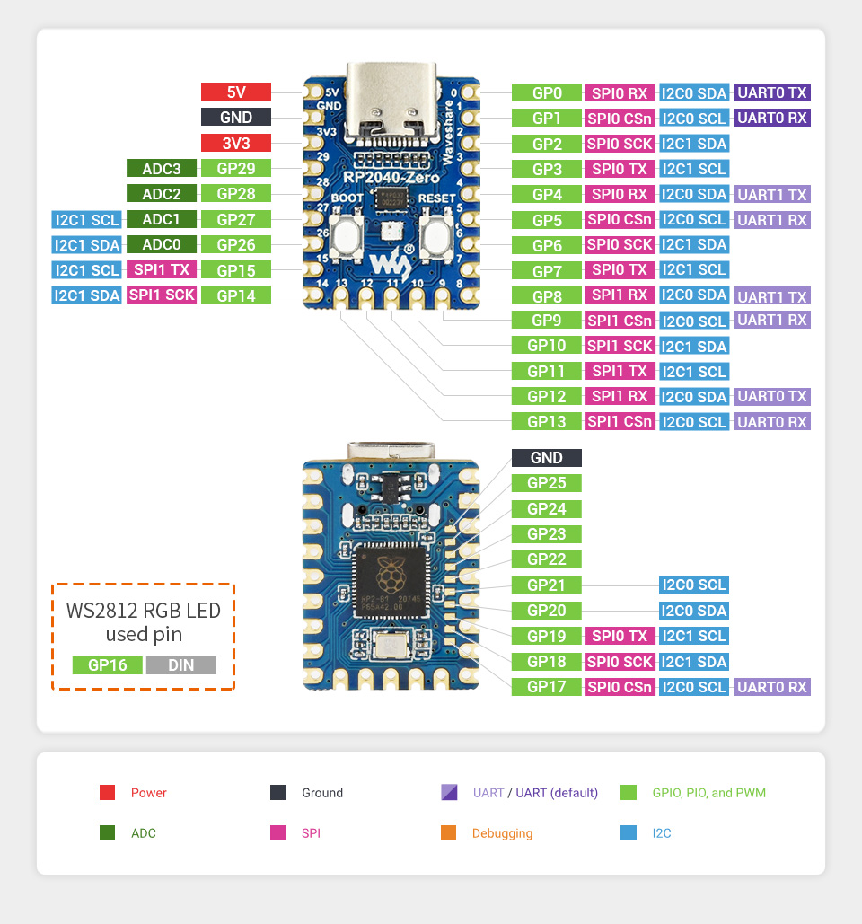 + +--- + +# Build phase +There are now no known unknowns in the project, now comes the grind. + +### Left side done + + + + + +Since i decided to use the first prototype, i had to retrofit the connector +outside the housing, meaning i had to design a new piece that a connector i +found, could be press fit into. + +### Left side done right side WIP + + +## Right side + + + + + + +When soldering the connector, i soldered wires to the connector first, then i +glued in indo place, so the wires could be routed and cut to distance. +All 20 trough-hole GPIO pins on the micro controller chip breakout are needed +for the 6 rows and 14 columns, but 2 GPIO are needed for I²C for the trackball. +So i needed to access the SMD pads on the back of the RP2040, which was some +small soldering, i used a flat cable to achive this. + +Another problem is that the prototyping PCB the microcontroller is mounted into +isn't used for wire management, but meerly to attatch it with screwable mounting +holes to the case. This means i have to have lot's of small wires in a tight +space this is where [Magnet wire](https://en.wikipedia.org/wiki/Magnet_wire) +comes into play. + +## Firmware build +[Setting Up Your QMK Environment](https://docs.qmk.fm/#/newbs) + +When creating a handwired keyboard, the convention is to place it +in `handwired/name` + +You might have to flip `diode_direction` in `info.json` if no keys work. +The options are `ROW2COL` and `COL2ROW` + + +### Customizing firmware +It's possible to [Customize Your Keyboard’s Behavior](https://docs.qmk.fm/#/custom_quantum_functions) +by writing a bit of C code. + +I've coded the following: + + - Change pointing device CPI. by clicking it + - Indicate pointing device mode with its RGB LED + - Normal + - Precise + - Scroll + - Volume + - Switch layout (Colemak, qwerty) + - Turn LEDs off when suspending / shutting down computer + - Middle mouse button only send button press on button up, if the user didn't scroll + +The way i figured out how to do something specific, +was a combination of reading the documentation, and greping through how other +keyboards in the `keyboards` directory does things. + +TODO Host, post and add link to GIT repo + +## Next challenge learning colemak + +It's a steep learning curve, but the finger movement, or lack there of for +typing English seems more sound. Set aside a weekend for learning where the +keys are, and be prepared to be frustrated at typing at 5 wpm, and slowly +working up from there. +It's a bit unfortunate that I'm changing multiple variables at the same time, +Namely learning touch typing, at the same time as i switch to colemak +and an ortholinear layout. Therefore i will not know which impact each has on +percieved finger health and typing speed. + +Also small rant about the legacy typewriter layout that sadly is the norm now +adays. How are you supposed to twist and contort your middle finger to reach +from D on the home row to C below when your hands are so close together that +they aren't straight. It feels more natural for my pointing finger to reach the +C button, because it aligns with the direction my hands are pointing. + +## Retrospective / Ideas for a version 2 + +### Work methodologies +Before starting a handwired keyboard project know that: + + - It's very labor intensive + - Hand wiring will take a long time especially if you make a split keeb, and choose to not use I²C between the halves. + - When prototyping something it's an itterative process, + which 3D printing plays very well into, as you can rapidly prototype, test ideas, and modify your design. + + +### Scrolling / volume rollers +Scrolling and adjusting volume with the trackball works great. +It would be awesome to explore this concept more, +by having a dedicated rotary encoder for it, perhaps two, +for quick onehanded volume adjustment, without holding the modifier (FN), +which is on the other side of the keyboard. + +### Device specific LED indicators +The LED in the pimoroni trackball works great to indicate which mode it's in. +So having dedicated LEDs for each device, +to indicate which mode it's in is a great to have. + +### LED indicators +They work great as a layer indicator. +Another idea is to add a photo resistor to dimm them in low ambient. + +### Pimoroni trackball +It's a really nifty little device, glad i tried it out, +but it's not precise enough for my taste. +It might be the QMK implementation (which already existed, which is nice), +It might be a hardware thing. Not sure, haven't read raw device output, +i assume default QMK settings are sane. +But next time around i want to try a different pointing device, +perhaps a ThinkPad trackpoint. + +### Connector / cable / wiring management +It worked fine for the time, since i had plenty of time to work on it now, +and didn't have to wait for components. +The process of hand wiring is labor intensive and tedious work. +Managing the wiring in a PCB and using chips in each half, +with standard cables would be preferable. +Then it's also possible to use longer cables to position the keyboard on either +side of a laptop, when using it on the go. +Taking up less space in one dimmension, but more in another, +by not having to move the laptop as far back, giving you flexibility. + +### Touch typing colorway +The keycaps can be colored to indicate which finger should be used. +This could also be done in software, if one chooses to add per key LEDs. + +### Standoffs on switch plate +Designing the standoffs into the switch plate might be desirable, since it +can make the cable wiring a bit easier, + +### Macro recording indicator +QMK Has the ability to record +[Dynamic macros](https://docs.qmk.fm/#/feature_dynamic_macros) +It would be cool to indicate the recording of such, by blinking the main +indicator LED red, this requires the ability to get +[milis()](https://www.arduino.cc/reference/en/language/functions/time/millis/) +or similar. + diff --git a/Custom keyboard/keycap_modification.jpg b/Custom keyboard/keycap_modification.jpg Binary files differnew file mode 100644 index 0000000..be2659f --- /dev/null +++ b/Custom keyboard/keycap_modification.jpg diff --git a/Custom keyboard/keycap_modification_printed.jpg b/Custom keyboard/keycap_modification_printed.jpg Binary files differnew file mode 100644 index 0000000..35114bc --- /dev/null +++ b/Custom keyboard/keycap_modification_printed.jpg diff --git a/Custom keyboard/left_side_bottom.jpg b/Custom keyboard/left_side_bottom.jpg Binary files differnew file mode 100644 index 0000000..c0366ff --- /dev/null +++ b/Custom keyboard/left_side_bottom.jpg diff --git a/Custom keyboard/left_side_connector_hotfix.jpg b/Custom keyboard/left_side_connector_hotfix.jpg Binary files differnew file mode 100644 index 0000000..b757fd7 --- /dev/null +++ b/Custom keyboard/left_side_connector_hotfix.jpg diff --git a/Custom keyboard/left_side_key_caps.jpg b/Custom keyboard/left_side_key_caps.jpg Binary files differnew file mode 100644 index 0000000..b28ad91 --- /dev/null +++ b/Custom keyboard/left_side_key_caps.jpg diff --git a/Custom keyboard/left_side_screws.jpg b/Custom keyboard/left_side_screws.jpg Binary files differnew file mode 100644 index 0000000..1d7b7ed --- /dev/null +++ b/Custom keyboard/left_side_screws.jpg diff --git a/Custom keyboard/left_side_testing.jpg b/Custom keyboard/left_side_testing.jpg Binary files differnew file mode 100644 index 0000000..f150f5d --- /dev/null +++ b/Custom keyboard/left_side_testing.jpg diff --git a/Custom keyboard/left_side_wip.jpg b/Custom keyboard/left_side_wip.jpg Binary files differnew file mode 100644 index 0000000..e477320 --- /dev/null +++ b/Custom keyboard/left_side_wip.jpg diff --git a/Custom keyboard/left_side_wiring_final.jpg b/Custom keyboard/left_side_wiring_final.jpg Binary files differnew file mode 100644 index 0000000..c9f04dc --- /dev/null +++ b/Custom keyboard/left_side_wiring_final.jpg diff --git a/Custom keyboard/main.jpg b/Custom keyboard/main.jpg Binary files differnew file mode 100644 index 0000000..caf69b3 --- /dev/null +++ b/Custom keyboard/main.jpg diff --git a/Custom keyboard/matrix_wiring.png b/Custom keyboard/matrix_wiring.png Binary files differnew file mode 100644 index 0000000..bea8e7f --- /dev/null +++ b/Custom keyboard/matrix_wiring.png diff --git a/Custom keyboard/progress_both_sides_missing_some_keycaps.jpg b/Custom keyboard/progress_both_sides_missing_some_keycaps.jpg Binary files differnew file mode 100644 index 0000000..2c7c09f --- /dev/null +++ b/Custom keyboard/progress_both_sides_missing_some_keycaps.jpg diff --git a/Custom keyboard/right_side_micro_controller_connector_wiring.jpg b/Custom keyboard/right_side_micro_controller_connector_wiring.jpg Binary files differnew file mode 100644 index 0000000..2c3a390 --- /dev/null +++ b/Custom keyboard/right_side_micro_controller_connector_wiring.jpg diff --git a/Custom keyboard/right_side_micro_controller_wiring.jpg b/Custom keyboard/right_side_micro_controller_wiring.jpg Binary files differnew file mode 100644 index 0000000..c89905f --- /dev/null +++ b/Custom keyboard/right_side_micro_controller_wiring.jpg diff --git a/Custom keyboard/right_side_wiring.jpg b/Custom keyboard/right_side_wiring.jpg Binary files differnew file mode 100644 index 0000000..1ee7dad --- /dev/null +++ b/Custom keyboard/right_side_wiring.jpg diff --git a/Custom keyboard/top_down.jpg b/Custom keyboard/top_down.jpg Binary files differnew file mode 100644 index 0000000..e3fa43d --- /dev/null +++ b/Custom keyboard/top_down.jpg diff --git a/Cyberdeck/Thumbnail.jpg b/Cyberdeck/Thumbnail.jpg Binary files differnew file mode 100644 index 0000000..0bc55a6 --- /dev/null +++ b/Cyberdeck/Thumbnail.jpg diff --git a/Cyberdeck/back.jpg b/Cyberdeck/back.jpg Binary files differnew file mode 100644 index 0000000..ad0f554 --- /dev/null +++ b/Cyberdeck/back.jpg diff --git a/Cyberdeck/index.md b/Cyberdeck/index.md new file mode 100644 index 0000000..6c58669 --- /dev/null +++ b/Cyberdeck/index.md @@ -0,0 +1,48 @@ +--- +description: "Computer" +created: 2023-03-08 +--- + +I want to build a cyberdeck, but isn't that just a weird cumbersome laptop... yes, that's not the point, think of it more as a weird retro inspired electronic simi functional experimental piece of art. + + + + +Back will house all the electronics and when the screen is lifted it's shown, i'll add an acrylic plate, which will help guide airflow from the fan through the device. +Will start with a Raspberry Pi, since that's what i have on hand, might change it out to a different SBC with proper NVME support instead of booting of an SD card, or USB adapter. + +## Ideas: +- Screen: Ultra wide screen IPS, smaller e paper display. +- Keyboard: Custom split ergonomic mechanical keyboard with trackball in the middle. +- Pointing device: Rollerball mouse + thinkpad like 3 buttons. +- Modular, expandable, with standard mounting interfaces, and electrically with ports ex. i2c expansion. +- Internal temperature on i2c. +- Modern retro vibe with vent slits. +- All PCB's in the back mounted to an insert plate, to avoid having to re-print the case. + +## Inspiration / resources: +- [Cyberdeck cafe](https://cyberdeck.cafe/mix/what-is-a-cyberdeck) +- [keyboard-layout-editor.com](http://www.keyboard-layout-editor.com/) +- [A Complete Guide to Building a Hand-Wired Keyboard](https://www.crackedthecode.co/a-complete-guide-to-building-a-hand-wired-keyboard/) +- [Power monitoring](https://www.youtube.com/watch?v=Qkx9M-AzznE) +- [OpenSCAD Keycap generator](https://www.thingiverse.com/thing:2783650/files) +### Cool cyberdecks: +- [Skeletal Cyberdeck](https://cyberdeck.cafe/mix/skeletal-cyberdeck) +- [TRL](https://cyberdeck.cafe/mix/trl-22121) +- [GRIZ](https://cyberdeck.cafe/mix/griz) +- [MSG](https://cyberdeck.cafe/mix/msg) +- [TTSD-3085](https://cyberdeck.cafe/mix/ttsd) +- [midknight8008](https://www.thingiverse.com/thing:4939019) + +## Parts: +- [Waveshare 10.4inch QLED Display 1600×720](https://www.waveshare.com/10.4hp-capqled.htm?sku=24646) +- [Waveshare 3S 5V 5A Output with i2c monitoring](https://www.waveshare.com/ups-module-3s.htm) +- [Trackball Breakout by Pimoroni](https://shop.pimoroni.com/products/trackball-breakout) +- [Flat HDMI cable](https://www.aliexpress.com/item/4000014554460.html) +- [1N4148 Diodes for keyboard switches](https://www.aliexpress.com/item/1005005435418695.html) +- [Adafruit KB2040 - RP2040 Kee Boar Driver](https://www.adafruit.com/product/5302) +- [Adafruit SHARP Memory Display Breakout - 2.7" 400x240 Monochrome](https://www.adafruit.com/product/4694) +- Keyboard switches +- Big ON/OFF switch +- External antenna + diff --git a/Cyberdeck/main.jpg b/Cyberdeck/main.jpg Binary files differnew file mode 100644 index 0000000..0dead12 --- /dev/null +++ b/Cyberdeck/main.jpg diff --git a/Electric longboard/Thumbnail.jpg b/Electric longboard/Thumbnail.jpg Binary files differnew file mode 100644 index 0000000..68a117e --- /dev/null +++ b/Electric longboard/Thumbnail.jpg diff --git a/Electric longboard/accident.jpg b/Electric longboard/accident.jpg Binary files differnew file mode 100644 index 0000000..c840109 --- /dev/null +++ b/Electric longboard/accident.jpg diff --git a/Electric longboard/batteries.jpg b/Electric longboard/batteries.jpg Binary files differnew file mode 100644 index 0000000..19fbabb --- /dev/null +++ b/Electric longboard/batteries.jpg diff --git a/Electric longboard/electronics.png b/Electric longboard/electronics.png Binary files differnew file mode 100644 index 0000000..4782a10 --- /dev/null +++ b/Electric longboard/electronics.png diff --git a/Electric longboard/electronics_side.png b/Electric longboard/electronics_side.png Binary files differnew file mode 100644 index 0000000..22d4f72 --- /dev/null +++ b/Electric longboard/electronics_side.png diff --git a/Electric longboard/index.md b/Electric longboard/index.md new file mode 100644 index 0000000..9635325 --- /dev/null +++ b/Electric longboard/index.md @@ -0,0 +1,19 @@ +--- +description: "A longboard with hub motors in the wheels, custom designed 3D printed enclosures and a custom battery" +created: 2022-11-08 +--- + + + + + + + + + + +The battery is a 10s 5p config. + + + +Got in an accident :( diff --git a/Electric longboard/main.jpg b/Electric longboard/main.jpg Binary files differnew file mode 100644 index 0000000..ff295f4 --- /dev/null +++ b/Electric longboard/main.jpg diff --git a/Electric longboard/side.png b/Electric longboard/side.png Binary files differnew file mode 100644 index 0000000..f0f9c76 --- /dev/null +++ b/Electric longboard/side.png diff --git a/Electric longboard/topdown.jpg b/Electric longboard/topdown.jpg Binary files differnew file mode 100644 index 0000000..6311b92 --- /dev/null +++ b/Electric longboard/topdown.jpg diff --git a/Game boy zero/Thumbnail.jpg b/Game boy zero/Thumbnail.jpg Binary files differnew file mode 100644 index 0000000..c403266 --- /dev/null +++ b/Game boy zero/Thumbnail.jpg diff --git a/Game boy zero/index.md b/Game boy zero/index.md new file mode 100644 index 0000000..e035f8e --- /dev/null +++ b/Game boy zero/index.md @@ -0,0 +1,25 @@ +--- +description: "A Raspberry PI fitted into a gameboy DMG-01 shell" +created: 2022-11-07 +--- + + + + +DMG-01 case with a Raspberry PI inside. + +## Parts list +- 3.5 Inch backup monitor +- TP4056 li-ion charge module with protection circuit +- Raspberry PI Zero W v1 + +## Problems, to address in a possible v2 +- Get's very hot on the screen, might be the power circuits behind it. +- Powers off abruptly after a while, low battery charge? +- No battery charge indication. +- Kinda jank placement of components. Glued not screwed, not as replacable. +- D-pad can register a different direction then the one pressed. +- Audio circuit can be turned up so high it abruptly shuts down the device (over current protection?). +- Audio circuit has no curcuits, just directly connected to GPIO. +- No brightness controls. +- Analogue, not digital display. diff --git a/Game boy zero/insides.jpg b/Game boy zero/insides.jpg Binary files differnew file mode 100644 index 0000000..75fbed8 --- /dev/null +++ b/Game boy zero/insides.jpg diff --git a/Game boy zero/main.jpg b/Game boy zero/main.jpg Binary files differnew file mode 100644 index 0000000..3cb6b8c --- /dev/null +++ b/Game boy zero/main.jpg diff --git a/How-to/Custom handwired keyboard.md b/How-to/Custom handwired keyboard.md new file mode 100644 index 0000000..b43ddcc --- /dev/null +++ b/How-to/Custom handwired keyboard.md @@ -0,0 +1,114 @@ +--- +description: Process of how to create a custom designed hardwired keyboard +created: 2024-03-01 +--- + +TODO ROUGH PRICE + +## Plan +Start out by getting a rough plan of what you want to make, so you can order parts, as takes a while, if you wish to do +it cheaply. + +First of all you need to decide how big your keyboard needs to be, do you wish to make an 100%, macropad, ultra-compact, +split, do you want dedicated buttons for all 24 function keys? none of the above? + +You can play around with [keyboard-layout-editor.com](http://www.keyboard-layout-editor.com/) to find a layout you like, +see different layout under "Preset" + +Massive repo of inspiration: [keebfolio.netlify.app](https://keebfolio.netlify.app/) + +### Switches +#### Design (Will affect keyboard design) +- Cherry MX design (classic, old, bulky, readily available, cloned into oblivion) +- Low profile? + - Kalih Choc (Expensive, different keycaps) + - Others + - [gateron.co - Gateron Low Profile 2.0 Mechanical Switch](https://www.gateron.co/products/gateron-low-profile-mechanical-switch-set) + - [keychron.com - Keychron Low Profile Mechanical Switch](https://www.keychron.com/products/keychron-low-profile-mechanical-switch) +Unsure, order a Switch tester or ask a friend to try their switches, to see what you like +#### Type +Generally there 3 types, originally made by cherry, I'd recommend none of them +- Clicky - Typically blue (obnoxious) +- Linear - Typically red (Did I press that button?) +- Tactile - Typically brown (Mushy) + +But do limit your scope enough, so you don't lose interest before completing the core project. +Be ready to test ideas feasibility and scrap them if infeasible. + +### Switch matrix +So what parts do you need? +You need to decide which method you wish to use, to wire up your switches +- Matrix with diodes (recommended method) + - Requires 1 diodes per switch, diodes are cheap + - Cable routing is more manageable +- Straight (1 wire per switch to microcontroller) + - Requires enough pins + +An I/O expander can be used to add additional pins to a microcontroller, it's also useful for split keyboards, +as it can require only 4 pins (I²C + power and ground) from the microcontroller + +## Order parts (Consumables) +### Checklist +#### Keyboard specific +- Switches +- Microcontroller, look at [QMK Compatible microcontrollers](https://docs.qmk.fm/#/compatible_microcontrollers), +i recommend a RP2040 based microcontroller +- Keycaps? Do you want to order these or [3D print them](#3d-printed-keycaps) +- Diodes [aliexpress.com - 1N4148](https://www.aliexpress.com/item/1005005435418695.html) +- Split keyboard parts + - I/O expander route + - I/O expander MCP23017 + - Connector [aliexpress.com - TRRS headphone jack](https://www.aliexpress.com/item/1005003146932723.html) + - Cable [aliexpress.com - TRRS headphone cable](https://www.aliexpress.com/item/1005001781279058.html) + +#### General maker +- 3D printed filament +- Solder tin +- Extra features? +Get wild, add an old [ThinkPad trackpoint](https://docs.qmk.fm/#/feature_ps2_mouse), +a [rollerball mouse](https://shop.pimoroni.com/products/trackball-breakout?variant=27672765038675), +rotary encoder, maybe LEDs. +- Heat shrink tube +- Magnet wire (can come in handy) + +### Tools - non consumables +- 3D printer +- Soldering iron +- Continuity tester (for debugging connections) +- + +## Waiting for parts +### Layout design finalisation +Staggered? +Ortholinear? +Something else entirely? + +[keyboard-layout-editor.com](http://www.keyboard-layout-editor.com/) + +[keyboard-layout-editor.com - My layout](http://www.keyboard-layout-editor.com/##@_backcolor=%23000000%3B&@_c=%230096a7&t=%23ffffff%0A%0A%0A%23ff8616%3B&=Esc%0A%0A%0AFnLock&_c=%236d6d6d%3B&=F1%0A%0A%0A%3Ci%20class%2F='fa%20fa-volume-off'%3E%3C%2F%2Fi%3E&=F2%0A%0A%0A%3Ci%20class%2F='fa%20fa-volume-down'%3E%3C%2F%2Fi%3E&=F3%0A%0A%0A%3Ci%20class%2F='fa%20fa-volume-up'%3E%3C%2F%2Fi%3E&=F4%0A%0A%0A%3Ci%20class%2F='fa%20fa-microphone-slash'%3E%3C%2F%2Fi%3E&=F5%0A%0A%0A%3Ci%20class%2F='fa%20fa-sun-o'%3E%3C%2F%2Fi%3E-&_x:3%3B&=F6%0A%0A%0A%3Ci%20class%2F='fa%20fa-sun-o'%3E%3C%2F%2Fi%3E+&=F7%0A%0A%0A%3Ci%20class%2F='fa%20fa-caret-left'%3E%3C%2F%2Fi%3E%3Ci%20class%2F='fa%20fa-caret-left'%3E%3C%2F%2Fi%3E&=F8%0A%0A%0A%3Ci%20class%2F='fa%20fa-play'%3E%3C%2F%2Fi%3E%3Ci%20class%2F='fa%20fa-pause'%3E%3C%2F%2Fi%3E&=F9%0A%0A%0A%3Ci%20class%2F='fa%20fa-caret-right'%3E%3C%2F%2Fi%3E%3Ci%20class%2F='fa%20fa-caret-right'%3E%3C%2F%2Fi%3E&_t=%23ffffff%3B&=F10&=F11&=F12&=Delete%3B&@_c=%23262626%3B&=%60%0A~&=1%0A!&=2%0A%2F@&=3%0A%23&=4%0A$&=5%0A%25&_x:3%3B&=6%0A%5E&_t=%23ffffff%0A%0A%0A%23ff8616%3B&=7%0A%2F&%0A%0A7&=8%0A*%0A%0A8&=9%0A%28%0A%0A9&=0%0A%29%0A%0A+&_t=%23ffffff%3B&=-%0A%2F_&=%2F=%0A+&_c=%236d6d6d%3B&=BckSp%3B&@=Tab&_c=%23262626%3B&=Q&=W&=E&=R&=T&_x:3%3B&=Y&_t=%23ffffff%0A%0A%0A%23ff8616%3B&=U%0A%0A%0A4&=I%0A%0A%0A5&=O%0A%0A%0A6&=P%0A%0A%0A%C3%97&_t=%23ffffff%3B&=%7B%0A%5B&=%7D%0A%5D&=%7C%0A%5C%3B&@_c=%236d6d6d&t=%23ffffff%0A%0A%0A%23ff8616%3B&=Comp%0A%0A%0ACapsL&_c=%23262626&t=%23ffffff%3B&=A&=S&=D&_n:true%3B&=F&=G&_x:3%3B&=H&_t=%23ffffff%0A%0A%0A%23ff8616&n:true%3B&=J%0A%0A%0A1&=K%0A%0A%0A2&=L%0A%0A%0A3&=%2F:%0A%2F%3B%0A%0A-&_t=%23ffffff%3B&=%22%0A'&_c=%230096a7&w:2%3B&=Enter%3B&@_c=%236d6d6d%3B&=Shift&_c=%23262626%3B&=Z&=X&=C&=V&=B&_x:3%3B&=N&_t=%23ffffff%0A%0A%0A%23ff8616%3B&=M%0A%0A%0A0&=%3C%0A,%0A%0A,&=%3E%0A.%0A%0A.&=%3F%0A%2F%2F%0A%0A%2F%2F&_c=%236d6d6d&t=%23ffffff%3B&=PgUp&_c=%23c1c1c1&t=%23000000%3B&=%E2%86%91&_c=%236d6d6d&t=%23ffffff%3B&=PgDn%3B&@=Ctrl&=Super&=Alt&_t=%23ff8616%3B&=Fn&_c=%23262626&t=%23ffffff&a:7&w:2%3B&=&_x:2&c=%23c1c1c1&t=%23000000&a:4%3B&=mous1&=mous2&=mous3&_c=%236d6d6d&t=%23ffffff%0A%0A%0A%23ff8616%3B&=Menu%0A%0A%0AInsert&=Home%0A%0A%0APrtSc&_t=%23ffffff%3B&=End&_c=%23c1c1c1&t=%23000000%3B&=%E2%86%90&_n:true%3B&=%E2%86%93&=%E2%86%92) + +## Other great guides + + +## Switch plate generation +### Testing fit + +### 3D printing +#### 3D printed keycaps + + +### Wiring test 3x3 +The best way to eliminate unknowns and avoid wasting work, is by wiring up a small part, and testing this + +### Firmware setup + + +### No unknowns, home run, final stretch, grind + +### Extra firmware features +Inspire, show opportunities +grep QMK repo + +### Show off + +### Get ideas for your next version
\ No newline at end of file diff --git a/How-to/Selfhost blog.md b/How-to/Selfhost blog.md new file mode 100644 index 0000000..1314774 --- /dev/null +++ b/How-to/Selfhost blog.md @@ -0,0 +1,29 @@ +--- +description: How to create, and self host a blog like this +created: 2024-03-01 +--- + +## Chose a static site generator +This is the tool that takes your [markdown](https://www.markdownguide.org/basic-syntax/) or other markup language, +and generates HTML files, these can then uploaded to a server to host. + +- [Hugo](https://gohugo.io/) +- [Pelican](https://getpelican.com/) +- [My custom one](https://git.node5.net/blog-generator/about/) + +## Buy a domain +### Chose a TLD (Top Level Domain) +.net is pretty cool IMO + +## Hosting + +- Selfhost + - At home + - Requires static IP + - Router port forward + - Always having a machine online + - Exposes your home IP (This isn't super bad) +- VPS (cloud monthly payment) + - Not independent + +For the rest of this I refer to the awesome guides at [landchad.net](https://landchad.net/) diff --git a/Power bank 20v USB-C PD/3d_model_plan.jpg b/Power bank 20v USB-C PD/3d_model_plan.jpg Binary files differnew file mode 100644 index 0000000..c49ec20 --- /dev/null +++ b/Power bank 20v USB-C PD/3d_model_plan.jpg diff --git a/Power bank 20v USB-C PD/Thumbnail.jpg b/Power bank 20v USB-C PD/Thumbnail.jpg Binary files differnew file mode 100644 index 0000000..2c03c67 --- /dev/null +++ b/Power bank 20v USB-C PD/Thumbnail.jpg diff --git a/Power bank 20v USB-C PD/battery_pack_back.jpg b/Power bank 20v USB-C PD/battery_pack_back.jpg Binary files differnew file mode 100644 index 0000000..1683af8 --- /dev/null +++ b/Power bank 20v USB-C PD/battery_pack_back.jpg diff --git a/Power bank 20v USB-C PD/battery_pack_back_2.jpg b/Power bank 20v USB-C PD/battery_pack_back_2.jpg Binary files differnew file mode 100644 index 0000000..1ca6f95 --- /dev/null +++ b/Power bank 20v USB-C PD/battery_pack_back_2.jpg diff --git a/Power bank 20v USB-C PD/battery_pack_front.jpg b/Power bank 20v USB-C PD/battery_pack_front.jpg Binary files differnew file mode 100644 index 0000000..4565eaa --- /dev/null +++ b/Power bank 20v USB-C PD/battery_pack_front.jpg diff --git a/Power bank 20v USB-C PD/case_model.png b/Power bank 20v USB-C PD/case_model.png Binary files differnew file mode 100644 index 0000000..1dfdd6c --- /dev/null +++ b/Power bank 20v USB-C PD/case_model.png diff --git a/Power bank 20v USB-C PD/electronics.jpg b/Power bank 20v USB-C PD/electronics.jpg Binary files differnew file mode 100644 index 0000000..f108091 --- /dev/null +++ b/Power bank 20v USB-C PD/electronics.jpg diff --git a/Power bank 20v USB-C PD/finished_bottom.jpg b/Power bank 20v USB-C PD/finished_bottom.jpg Binary files differnew file mode 100644 index 0000000..a88350e --- /dev/null +++ b/Power bank 20v USB-C PD/finished_bottom.jpg diff --git a/Power bank 20v USB-C PD/finished_lcd.jpg b/Power bank 20v USB-C PD/finished_lcd.jpg Binary files differnew file mode 100644 index 0000000..a5cc3ce --- /dev/null +++ b/Power bank 20v USB-C PD/finished_lcd.jpg diff --git a/Power bank 20v USB-C PD/finished_top.jpg b/Power bank 20v USB-C PD/finished_top.jpg Binary files differnew file mode 100644 index 0000000..b75d13b --- /dev/null +++ b/Power bank 20v USB-C PD/finished_top.jpg diff --git a/Power bank 20v USB-C PD/index.md b/Power bank 20v USB-C PD/index.md new file mode 100644 index 0000000..e187a6a --- /dev/null +++ b/Power bank 20v USB-C PD/index.md @@ -0,0 +1,104 @@ +--- +description: "Laptop power bank" +created: 2022-11-13 +--- + + + +A DIY power bank with 20v USB type C power-delivery. +I had a bunch of 18650's from a previous project, +that were no longer in use... see [Electric longboard](/Electric longboard) + +## Parts list: + - [20V USB C PD Bidi buck boost converter](https://www.aliexpress.com/item/1005004629297118.html) + - [18650 holders](https://www.aliexpress.com/item/1005002749793325.html) + - [Heatsinks](https://www.aliexpress.com/item/32969500753.html) + - [USB C PD tester](https://www.aliexpress.com/item/1005002767097993.html) + - [4S li-ion BMS with balancing](https://www.aliexpress.com/item/1005001916022803.html) + - [Battery capacity display](https://www.aliexpress.com/item/4000448424977.html) + - Samsung-30q 18650 li-ion batteries (got these from a trustworthy local seller) + +## Plan + + + + +The battery pack is designed as a 4s 3p pack (4 in series and 3 in parallel). +So the batteries will be connected altering + and - every 3 cells. + +## Component testing + + + +I've tested the electronic components by connecting the bare minimum of batteries 4s 1p. +You have to connect power the the board once, and then it works. +I used a USB c PD trigger board to test the PD capability. +It works, but the buck boost converter coil gets very hot, +even with the heatsink on. Will have to use a bigger heatsink for it. +Possibly on the back, though i need to insulate 2 points on the back, +that aren't part of the ground plane, like the rest of the back. +The mosfets on the BMS don't heat up, +could probably go without the heatsinks. +I also need to design a case and 3D print it. +The setup works but i'm worried about a short before the BMS. +So i will probably redo the wiring. + + + +Redid the wiring with the lessons learned during testing, +and based on feedback from others. +The Bi-Di module only seems to heat up when stepping down the voltage a lot, +i think the current cooling will be adequate. + +Someone just showed me an even better, but more expensive board: +[100W PD and 120W DC power bank module](https://www.aliexpress.com/item/1005004508048246.html) +maybe for a future powerbank. + +## Designing enclosure + + + + +After learning [FreeCAD](https://www.freecadweb.org/), +i designed and 3D printed a case. +It's designed to use a transparent acrylic as the top and bottom. +You can download the model files here: +TODO Add files +[FreeCAD Model](/files/powerbank/POWERBANK.FCStd), [BackPart](/files/powerbank/POWERBANK-part1.stl), +[FontPart](/files/powerbank/POWERBANK-part2.stl),[Button](/files/powerbank/POWERBANK-button.stl) + + + + + +Printed the case. The fit seems great +I mounted the screen with some double sided tape, +some screws that i heated up with my soldering iron, and some glue. +I also shortened the button on the screen and put in a 3d printed button. +Seems to click OK, and it's recessed a bit, +so it won't be turned on accidentally. + + + + + +## Future ideas + - I think the screws are too close to the edge, so i got a new idea. + 3D print a cover out of TPU for all the edges. + - It would be really cool to add a micro controller with power messurement, + and an LED strip displaying the remaining charge. + +## Laser cut acrylic sheets + + + + +Some fellow hackers were super kind, to laser cut acrylic sheets for me, +that has this cool reflective film that changes color based on the angle of the light. +It features ventilation holes for the PD module and engraved text. +It's way more precise, and the side of the cut is super clear. + +## External links: + - [youtube.com - BMS explanation video](https://www.youtube.com/watch?v=QNENyu97w2A) + - [youtube.com - GreatScott! PD module video](https://www.youtube.com/watch?v=_WI9Nwqvplo) + diff --git a/Power bank 20v USB-C PD/laser_cut_lcd.jpg b/Power bank 20v USB-C PD/laser_cut_lcd.jpg Binary files differnew file mode 100644 index 0000000..57420fa --- /dev/null +++ b/Power bank 20v USB-C PD/laser_cut_lcd.jpg diff --git a/Power bank 20v USB-C PD/laser_engraved_node5.net.jpg b/Power bank 20v USB-C PD/laser_engraved_node5.net.jpg Binary files differnew file mode 100644 index 0000000..299941d --- /dev/null +++ b/Power bank 20v USB-C PD/laser_engraved_node5.net.jpg diff --git a/Power bank 20v USB-C PD/lcd.jpg b/Power bank 20v USB-C PD/lcd.jpg Binary files differnew file mode 100644 index 0000000..d5dfbb7 --- /dev/null +++ b/Power bank 20v USB-C PD/lcd.jpg diff --git a/Power bank 20v USB-C PD/main.jpg b/Power bank 20v USB-C PD/main.jpg Binary files differnew file mode 100644 index 0000000..c1b7050 --- /dev/null +++ b/Power bank 20v USB-C PD/main.jpg diff --git a/Power bank 20v USB-C PD/print.jpg b/Power bank 20v USB-C PD/print.jpg Binary files differnew file mode 100644 index 0000000..2056fe6 --- /dev/null +++ b/Power bank 20v USB-C PD/print.jpg diff --git a/Power bank 20v USB-C PD/usb_c_connector.jpg b/Power bank 20v USB-C PD/usb_c_connector.jpg Binary files differnew file mode 100644 index 0000000..d0faf17 --- /dev/null +++ b/Power bank 20v USB-C PD/usb_c_connector.jpg diff --git a/QMK firmware keychron c1/Thumbnail.jpg b/QMK firmware keychron c1/Thumbnail.jpg Binary files differnew file mode 100644 index 0000000..29d7d4d --- /dev/null +++ b/QMK firmware keychron c1/Thumbnail.jpg diff --git a/QMK firmware keychron c1/index.md b/QMK firmware keychron c1/index.md new file mode 100644 index 0000000..0933cd5 --- /dev/null +++ b/QMK firmware keychron c1/index.md @@ -0,0 +1,93 @@ +--- +description: "Flashing Sonix QMK on Keychron C1 plain mechanical keyboard" +created: 2023-10-21 +--- + + + +Base instructions: [Sonix QMK sn32_master Keychron C1 plain](https://github.com/SonixQMK/qmk_firmware/tree/sn32_master/keyboards/keychron/c1/plain) + +## Keyboard hardware model variants +- [Keychron C1 plain (No LEDs)](https://www.keychron.com/products/keychron-c1-wired-mechanical-keyboard?variant=39767302078553) +and +- [Keychron C1 white (White LEDs)](https://www.keychron.com/products/keychron-c1-wired-mechanical-keyboard?variant=32321246953561) +use the same board. +- [Keychron C1 RGB (RGB LEDs)](https://www.keychron.com/products/keychron-c1-wired-mechanical-keyboard?variant=32321247051865) +uses a different board + +This tutorial / collection of info applies to Keychron C1 plain + +## Building QMK firmware + +The correct [Sonix QMK](https://sonixqmk.github.io/SonixDocs/) +branch to use for this is +[sn32_master_stable](https://github.com/SonixQMK/qmk_firmware/tree/sn32_master) +source: Found a comment on the discord server, generally digging through the +[discord server](https://discord.gg/8XqzfBknfC) reveals the correct way of +doing something +```bash +qmk clone SonixQMK/qmk_firmware -b sn32_master_stable +``` + + +When making the firmware with the QMK command, +specify `via` as the layout +```bash +qmk compile --keyboard keychron/c1/plain --keymap via +``` + +## Build Sonix flasher + +It's important to use the +[Flashing tool](https://github.com/SonixQMK/sonix-flasher) to flash the +jumploader, which is needed on this chip, because it's possible to brick it, +by overwriting the bootloader, the jumploader allows a button combination (ESC) +to be held when plugging in the keyboard to boot into bootloader mode. +Bootloader mode is the mode that allows flashing new software to the chip. + +To build on modern systems, update requirements.txt QT version as per the +instructions [here](https://github.com/cederlys/svive-qmk#flashing) +(I do this with sed in the following code snippet) + +This was tested on Arch 2023-09-21 with the following package versions: + + - [python36](https://aur.archlinux.org/packages/python36) 3.6.15-5 + - [qt5-base](https://archlinux.org/packages/extra/x86_64/qt5-base/) 5.15.10+kde+r155-1 + - [python-pyqt5](https://archlinux.org/packages/extra/x86_64/python-pyqt5) 5.15.9-2 + +```bash +# Install python 3.6 +yay -Sy python36 + +# Don't save the software when rebooting the computer +cd /tmp/ + +# Download release 0.2.5 +wget https://github.com/SonixQMK/sonix-flasher/archive/refs/tags/v0.2.5.zip + +# Extract release +unzip v0.2.5.zip +cd sonix-flasher-0.2.5/ + +# Install these python package versions for this project only +python3.6 -m venv venv +source venv/bin/activate + +# This was needed, else it threw an error +pip3 install --upgrade pip +pip install wheel + +# Use a more modern version of the QT package, +# that's compatible with the version of QT in the repos +sed -i 's/hidapi==0.9.0.post2/hidapi==0.14.0/' requirements.txt +pip install -r requirements.txt + +# Run the program +python src/main/python/main.py +``` + +## VIA +To use via it needs the json keyboard definition loaded + +## Resources +- [C1 White PCB info](https://github.com/IsaacDynamo/keychron_c1_white_info) diff --git a/QMK firmware keychron c1/main.jpg b/QMK firmware keychron c1/main.jpg Binary files differnew file mode 100644 index 0000000..913f725 --- /dev/null +++ b/QMK firmware keychron c1/main.jpg diff --git a/Raspberry Pi cooling/Thumbnail.jpg b/Raspberry Pi cooling/Thumbnail.jpg Binary files differnew file mode 100644 index 0000000..c1aa439 --- /dev/null +++ b/Raspberry Pi cooling/Thumbnail.jpg diff --git a/Raspberry Pi cooling/case.jpg b/Raspberry Pi cooling/case.jpg Binary files differnew file mode 100644 index 0000000..ac00f48 --- /dev/null +++ b/Raspberry Pi cooling/case.jpg diff --git a/Raspberry Pi cooling/graph.png b/Raspberry Pi cooling/graph.png Binary files differnew file mode 100644 index 0000000..8efbf4c --- /dev/null +++ b/Raspberry Pi cooling/graph.png diff --git a/Raspberry Pi cooling/index.md b/Raspberry Pi cooling/index.md new file mode 100644 index 0000000..bc2b388 --- /dev/null +++ b/Raspberry Pi cooling/index.md @@ -0,0 +1,12 @@ +--- +description: "Comparison of combos of stock, fan and heatsink" +created: 2022-11-10 +--- + + + +3D printed raspberry pi case with an undervolted fan, and heatsinks. + + + + diff --git a/Raspberry Pi cooling/main.jpg b/Raspberry Pi cooling/main.jpg Binary files differnew file mode 100644 index 0000000..c93bdae --- /dev/null +++ b/Raspberry Pi cooling/main.jpg diff --git a/Seven segment display/CAD/Box/7 segment display box lid.stl b/Seven segment display/CAD/Box/7 segment display box lid.stl Binary files differnew file mode 100644 index 0000000..7197f88 --- /dev/null +++ b/Seven segment display/CAD/Box/7 segment display box lid.stl diff --git a/Seven segment display/CAD/Box/7 segment display box.FCStd b/Seven segment display/CAD/Box/7 segment display box.FCStd Binary files differnew file mode 100644 index 0000000..5f14e25 --- /dev/null +++ b/Seven segment display/CAD/Box/7 segment display box.FCStd diff --git a/Seven segment display/CAD/Box/7 segment display box.stl b/Seven segment display/CAD/Box/7 segment display box.stl Binary files differnew file mode 100644 index 0000000..c4367a8 --- /dev/null +++ b/Seven segment display/CAD/Box/7 segment display box.stl diff --git a/Seven segment display/CAD/Digit/7 segment display bottom.stl b/Seven segment display/CAD/Digit/7 segment display bottom.stl Binary files differnew file mode 100644 index 0000000..9c414f1 --- /dev/null +++ b/Seven segment display/CAD/Digit/7 segment display bottom.stl diff --git a/Seven segment display/CAD/Digit/7 segment display top diffuser.stl b/Seven segment display/CAD/Digit/7 segment display top diffuser.stl Binary files differnew file mode 100644 index 0000000..9af4d3f --- /dev/null +++ b/Seven segment display/CAD/Digit/7 segment display top diffuser.stl diff --git a/Seven segment display/CAD/Digit/7 segment display.FCStd b/Seven segment display/CAD/Digit/7 segment display.FCStd Binary files differnew file mode 100644 index 0000000..a511504 --- /dev/null +++ b/Seven segment display/CAD/Digit/7 segment display.FCStd diff --git a/Seven segment display/Diffusion test.jpg b/Seven segment display/Diffusion test.jpg Binary files differnew file mode 100644 index 0000000..d1c8530 --- /dev/null +++ b/Seven segment display/Diffusion test.jpg diff --git a/Seven segment display/Main.jpg b/Seven segment display/Main.jpg Binary files differnew file mode 100644 index 0000000..b0fa1ed --- /dev/null +++ b/Seven segment display/Main.jpg diff --git a/Seven segment display/Minute fade.mp4 b/Seven segment display/Minute fade.mp4 Binary files differnew file mode 100644 index 0000000..986d78b --- /dev/null +++ b/Seven segment display/Minute fade.mp4 diff --git a/Seven segment display/Segments wired.jpg b/Seven segment display/Segments wired.jpg Binary files differnew file mode 100644 index 0000000..2e44b03 --- /dev/null +++ b/Seven segment display/Segments wired.jpg diff --git a/Seven segment display/Thumbnail.jpg b/Seven segment display/Thumbnail.jpg Binary files differnew file mode 100644 index 0000000..53493dc --- /dev/null +++ b/Seven segment display/Thumbnail.jpg diff --git a/Seven segment display/Timelapse.mp4 b/Seven segment display/Timelapse.mp4 Binary files differnew file mode 100644 index 0000000..8612d7d --- /dev/null +++ b/Seven segment display/Timelapse.mp4 diff --git a/Seven segment display/index.md b/Seven segment display/index.md new file mode 100644 index 0000000..84dbac4 --- /dev/null +++ b/Seven segment display/index.md @@ -0,0 +1,88 @@ +--- +description: "Big 3D printed RGB LED seven segment display clock" +created: 2023-11-14 +--- + + + +## Links +- [Firmware source code - GIT](https://git.node5.net/firmware/seven-segment-display/) My custom C++ firmware check this out +- [youtube.com - Segmented Displays by Posy](https://www.youtube.com/watch?v=RTB5XhjbgZA) +- [Wikipedia Seven-segment display](https://en.wikipedia.org/wiki/Seven-segment_display) Contains standard segment naming +- [Segment design SVGs](http://www.michieldb.nl/other/segments/) + +## Parts +- [WS2811 Aliexpress White PCB Ordinary, 5m 60 IP30](https://www.aliexpress.com/item/2000165819.html) + +# Design / planing / idea phase +I got further interested in 7-segmented displays after a fellow hacker made a project with it, +and i wanted to explore my fondness of this delightful concept. +I decided to make a clock with it, but this is a concept that has been done before. +So i wanted some twist on the concept, and remembered this wonderful video: +[youtube.com - Segmented Displays by Posy](https://www.youtube.com/watch?v=RTB5XhjbgZA). +Hence i chose a design (Classic black) optimized for displaying numbers, but also one that still retained the boxy look. +Credit to the designer [Michiel de Boer(Posy)](http://www.michieldb.nl/). + +TODO Wire diagram + +## Diffusion + + + +I tested both clear and white PLA with different layer heights by printing squares. Then i moved onto the distance. +I determeined 2 layers of white PLA at a distance of 1.5 cm. was a good compromise. + +## CAD + +### Files +- Project box + - [Box - FreeCAD](CAD/Box/7 segment display box.FCStd) + - [Box - STL](CAD/Box/7 segment display box.stl) + - [Lid - STL](CAD/Box/7 segment display box lid.stl) +- Digit + - [Digit - FreeCAD](CAD/Digit/7 segment display.FCStd) + - [Digit top diffuser - STL](CAD/Digit/7 segment display top diffuser.stl) + - [Digit bottom - STL](CAD/Digit/7 segment display bottom.stl) + +### Digits +I used FreeCAD to design a bottom and top piece based on the SVG files. + +### Box +I used [this GRABCAD model](https://grabcad.com/library/arduino-dc-barrel-jack-2-1mm-for-kicad-1) +License: [GRABCAD Non-Comercial Licenses](https://help.grabcad.com/article/246-how-can-models-be-used-and-shared) +TODO Add picture of DC barreljack + +## Wiring + + + +## Firmware + +### Fading effect +<video controls style="width: 100%"> + <source src="Minute fade.mp4" type="video/mp4"> + Your browser does not support the video tag. +</video> + +I chose to add a slow fade effect as to not disturb ones peripheral vision. + +### Color change timelapse +<video controls style="width: 100%"> + <source src="Timelapse.mp4" type="video/mp4"> + Your browser does not support the video tag. +</video> + +The color changes hue overtime, but it does so slowly, as to not be noticeable. + +I've later changed this color hue to be derived from the time of day, +so it will always have the same color at the same time of day. +This change was easy to implement, due to my use of [HSV](https://en.wikipedia.org/wiki/HSL_and_HSV) See +[this commit](https://git.node5.net/firmware/seven-segment-display/commit/?id=99da4c6eb43516c266fb33dc84d43d5d6f655464) + +Now your brain can become wired to think, wow the clock is red, it's pretty late, i should go home. + +### Hour change animation + +I've also added a rainbow vomit animation once an hour, that intentionally grabs your attention, +to make you more aware of the passing time. As it's easy to lose track of time. + diff --git a/Sharp memory display/Holding jig.jpg b/Sharp memory display/Holding jig.jpg Binary files differnew file mode 100644 index 0000000..4fa7355 --- /dev/null +++ b/Sharp memory display/Holding jig.jpg diff --git a/Sharp memory display/Thumbnail.jpg b/Sharp memory display/Thumbnail.jpg Binary files differnew file mode 100644 index 0000000..0f2ccac --- /dev/null +++ b/Sharp memory display/Thumbnail.jpg diff --git a/Sharp memory display/index.md b/Sharp memory display/index.md new file mode 100644 index 0000000..78f2173 --- /dev/null +++ b/Sharp memory display/index.md @@ -0,0 +1,43 @@ +--- +description: LS012B7DH02 +created: 2024-01-19 +--- + + + +Collection of information regarding the sharp memory display `LS012B7DH02` +For memorization and referring back to. + +## Summarization of the datasheet information + +### Precautions + - Don't excessively bend the connector. + - If displaying a static image for a prologed time, refresh every 2 hours to avoid burn in? + - It's made of glass + - Clean with isopropyl alcohol + - Don't glue it + - UV / Sunlight exposure bad :/ but how bad? time will test this assertion + - Static electricity might cause pixels to not be shown, update frequently to reconcile LCD coagulates at low temperatures, room temperature is optional + - Place controller driver near LCD due to impedance + +### Specs + - View port 1.20” + - 240x240 pixels + - [TFT LCD](https://en.wikipedia.org/wiki/TFT_LCD) + - Dot pitch 0.127mm + - Size: 35.78 (W) × 36.53 (H) × 1.605 (D) + - Hardness: 3H + +### Pinout +Terminal | Symbol | I/O | Configurations | Function | Remark +-------- | ------ | ---- | -------------- | -------- | ------ +1 | SCLK | INPUT | NoPull | Serial clock signal | +2 | SI | INPUT | NoPull | Serial data input signal | +3 | SCS | INPUT | NoPull | Chip select signal ( Active of Hi ) | +4 | EXTCOMIN | INPUT | NoPull | External COM inversion signal input ( Square wave) | 【Note 4-2】 +5 | DISP | INPUT | NoPull | Display ON/OFF signal | 【Note 4-1】 +6 | VDDA | POWER | - | Power supply (Analog) | +7 | VDD | POWER | - | Power supply (Digital) | +8 | EXTMODE | INPUT | NoPull | Control mode of COM inversion is select terminal | 【Note 4-2】 +9 | VSS | GND | - | GND (Digital) | +10 | VSSA | GND | - | GND (Analog) | |


